184 KENR9126
Troubleshooting Section
g02186513
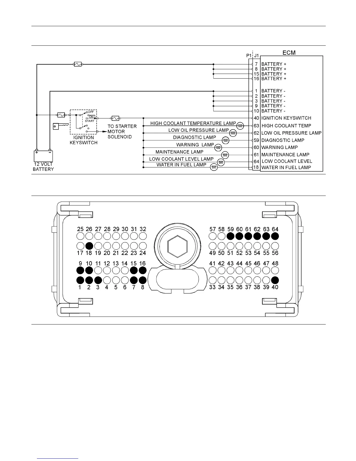
Illustration 73
Typical s chem atic of the indicator lamp circuit
g02186514
Illustration 74
Typical exam ple of the pin locations on the P1 connector
(1) Ground
(2) Ground
(3) Ground
(9) Ground
(10) Ground
(7) Battery+
(8) Ba t tery+
(15) Battery+
(16) Battery+
(18) Water in fuel lamp
(40) Keyswitch
(59) Diagnostic lamp
(60) Warning lamp
(61) Ma intenance lamp
(62) Low oil pressure lamp
(63) High coolant temperature lamp
(64) Low coolant level lamp
Test Step 1. Inspect Electrical Connectors
and Wiring
A. Turn the keyswitch to the OFF position.
B. Thoroug hly inspect P1 connector and the lamp
connections. Refer to Troubleshooting, “Electrical
Connectors - Inspect” for details.
C. Perform a 45 N (10 lb) pull test on each of
the wires in the customer connector and the
Electronic Control Module (ECM) connector that is
associated with the diagnostic lamp.
D. Check the screw for the P1 connector for the
correct torque of 5.0 N·m (44 lb in).
E. Check the harness for abrasions and for pinch
points from the battery to the ECM.