KENR9126 199
Troubleshooting Section
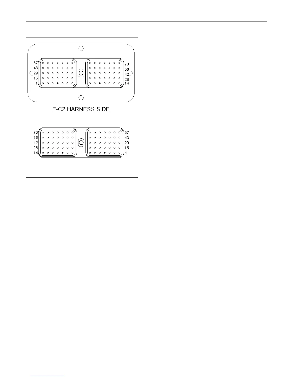
g02201013
Illustr
ation 84
Term inals that are associated with the throttle position sensor
(10) Primary throttle position
(4) Secondary throttle position
C. Perfor
m a 45 N (10 lb) pull test on each of the
wires that are associated with the throttle position
sensor.
D. Check the allen head screw on the customer
connector and on each ECM connector for the
prope
r torque. Refer to diagnostic functional tests
Troubleshooting, “Electrical Connectors - Inspect”
for the correct torque values.
E. Check the harness and wiring for abrasions and
for pinch points from each throttle position sensor
to th
eECMandfromthethrottlepositionsensor
to the electrical power source.
Expe
cted Result:
All connectors, pins, and sockets are completely
cou
pled and/or inserted, and the harness and wiring
are free of corrosion, of abrasion or of pinch points.
Res
ults:
•
OK – The wiring and the connectors appear to be
OK
. Proceed to Test Step 3.
•
Not OK – There is a problem with the wiring and/or
th
e connectors.
Repair: Repair the wiring and/or the connectors.
Replace parts,
if necessary. Ensure that all of the
seals are properly connected. Verify that the repair
eliminates the problem.
STOP.
Test Step 3. C
heck for Supply Voltage at
the Throttl
e P osition Sensor
A. Disconnect the harness connector from the
suspect thr
ottle position sensor.
B. Restore the electrical power to the ECM.
C. Measure the voltage between terminals A and B
on the harness connector for the throttle position
sensor.
Expected Result:
The supply voltage is at least 11 VDC for a 12 volt
system. The supply voltage is at least 22 VDC for a
24 volt s
ystem.
Results:
•
OK – The supply voltage is at least 11 VDC for a
12 volt system. The supply voltage is at least 22
VDC for
a 24 volt system. The supply voltage is
reaching the sensor. Proceed to Test Step 4.
•
Not OK –
The supply voltage is incorrect.
Repair: The configuration of the wiring between
the ba
ttery and the throttle position sensor depends
on the vessel's configuration. The problem could
be in the wiring or in a connector. There may be a
probl
em with the battery.
Perform the necessary repairs. Verify that the
prob
lem is resolved.
STOP.
Test Step 4. Check the Signal Wire fo r a
Short Circuit
A. Rem
ove the electrical power from the ECM.
B. Disconnect the P1 connector from every ECM on
th
e vessel. Verify that the electrical connector
for the suspect throttle position sensor is
disconnected.
Note: Be sure to wiggle the harnesses during the
following measurements. Be sure to wiggle each
h
arness near each connector.
C. Measure the resistance between terminal P1-53
a
nd all of the other terminals in the P1 connector
for the ECM that activated the -08 diagnostic code.