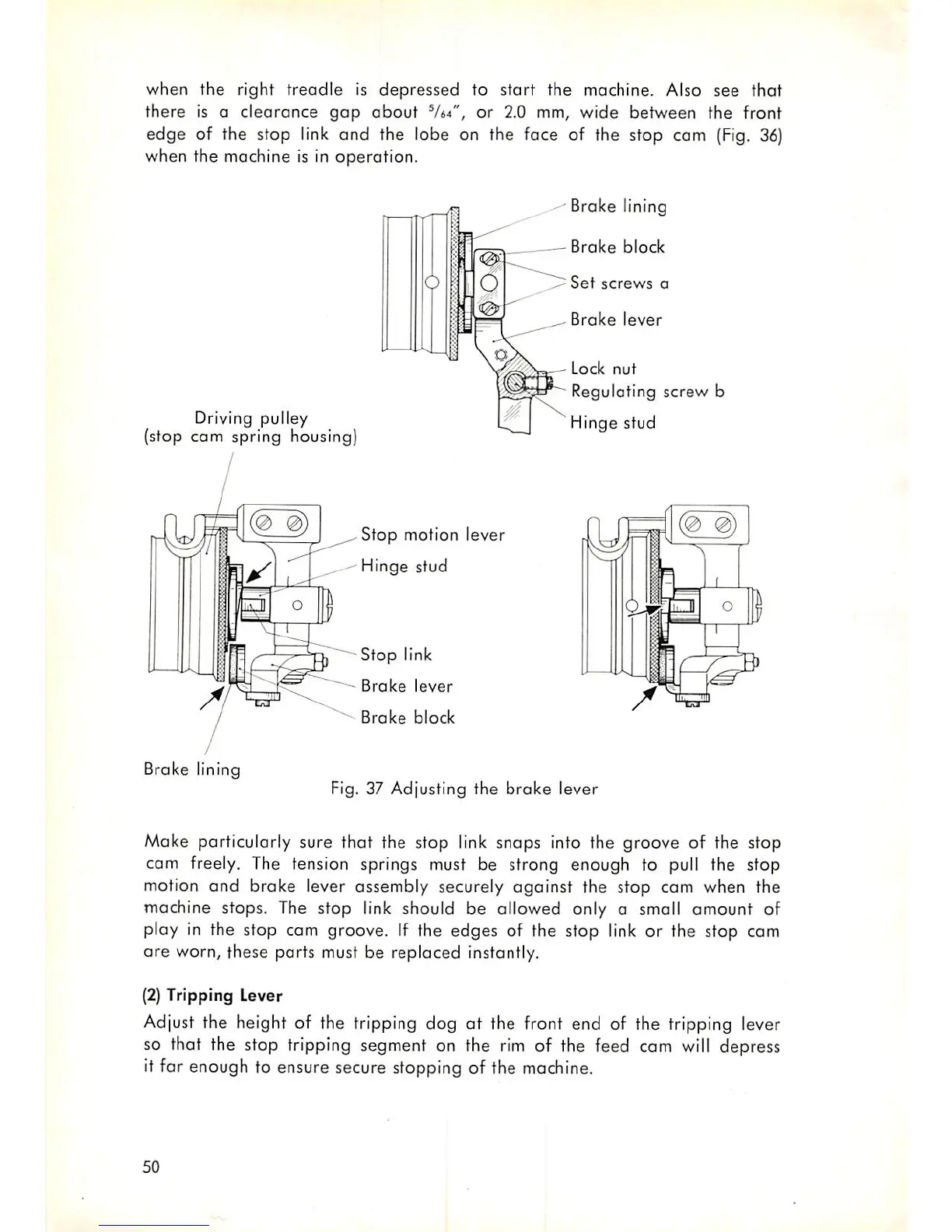
when the right treadle is depressed to start the machine. Also see that
there is a clearance
gap
about
^U*",
or 2.0 mm, wide between the front
edge of the stop
link
and the lobe on the foce of the stop cam
(Fig.
36)
when the machine is in operation.
Driving pulley
(stop cam spring housing)
(0 0)
K
(
i
•
Stop
motion lever
Hinge
stud
Stop
link
-
Brake
lever
Brake
block
Brake lining
Brake
block
Set
screws
a
Brake
lever
Lock
nut
Regulating
screw
b
Hinge
stud
OJ
Brake lining
Fig. 37 Adjusting the
brake
lever
Make particularly sure that the stop link snaps into the groove of the stop
cam freely. The tension springs must be strong enough to pull the stop
motion
and
brake lever assembly securely
against
the stop cam when the
machine stops. The stop link should be allowed only a small omount of
play in the stop cam groove. If the edges of the stop link or the stop cam
are worn, these ports must be replaced instantly.
(2)
Tripping Lever
Adjust the height of the tripping dog at the front end of the tripping lever
so that the stop tripping segment on the rim of the feed cam will depress
it far enough to ensure secure stopping of the machine.
50