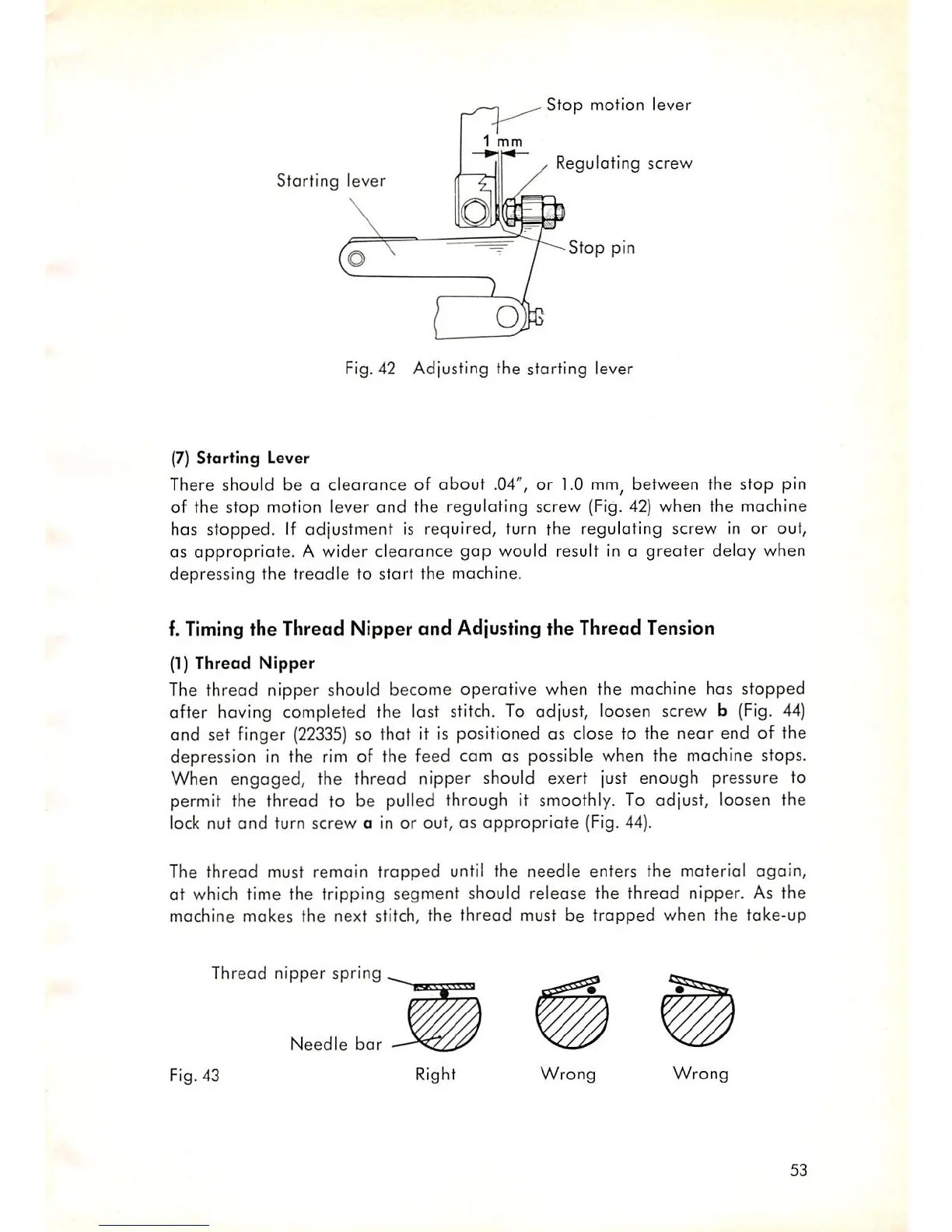
Stop
motion lever
1
mm
Starting
lever
Regulating
screw
—/^--Sfop
pin
Fig. 42 Adjusting the starting lever
(7)
Starting
Lever
There should be a clearance of about .04", or 1.0
mm,
between the stop pin
of the stop motion lever
and
the reguloting screw
{Fig.
42) when the machine
has
stopped.
If
adjustment
is required, turn the regulating screw in or out,
OS
appropriate. A wider clearance
gap
would result in a greater delay when
depressing the treadle to start the machine.
f.
Timing
the Thread Nipper
and
Adjusting the Thread Tension
(1) Thread
Nipper
The thread nipper should become operative when the machine has stopped
after having completed the last stitch. To adjust, loosen screw b (Fig. 44)
and set finger
(22335)
so that it is positioned as close to the near end of the
depression in the rim of the feed cam as possible when the machine stops.
When
engaged,
the thread nipper should exert just enough pressure to
permit the thread to be pulled through it smoothly. To adjust, loosen the
lock nut
and
turn
screw
a in or out, as
appropriate
(Fig. 44).
The
thread
must remoin
trapped
until the
needle
enters the material
again,
ot which time the tripping segment should release the thread nipper. As the
machine
makes
the
next stitch, the
thread
must be
trapped
when
the
take-up
Thread nipper spring
Needle
bar
Fig. 43
Right
Wrong
Wrong
53