4. Mounting
and
Adjustment Procedures
a.
Switch
ES
Attach
switch
ES
to
bearing
bracket
of
starting
lever.
On
machines
supplied
previously, drill screwholes inthe positions indicated in
Fig.
78.
Recent
machines
ore
provided with
appropriate
holes.
b.
Lever
B
On
previous
machines,
lever
B
should
be
mounted
as
shown
in
Fig.
79.
Re
cent
machines
are so designed that the
lever
con be
easily
screwed
on
with
two
fillister
head
screws.
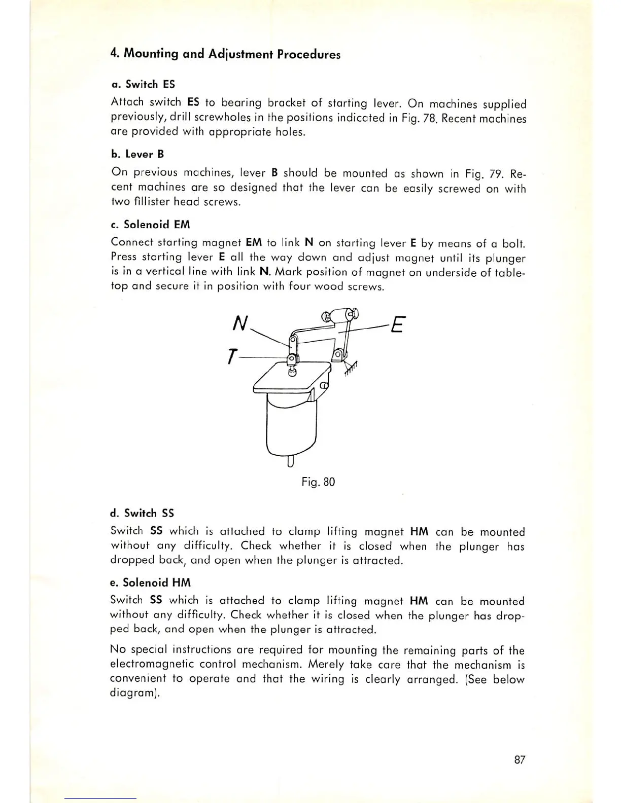
c.
Solenoid
EM
Connect starting magnet
EM
to link N on starting lever E by means of a bolt.
Press
starting lever E all the way down and adjust magnet
until
its plunger
is in a vertical linewith link N.Mork position of magnet on underside of table-
top
and
secure it in position with four
wood
screws.
Fig. 80
d.
Switch
SS
Switch
SS which is attached to clomp lifting magnet HM can be mounted
without any
difficulty.
Check
whether it is closed when the plunger has
dropped bock, and open when the plunger is attracted.
e.
Solenoid
HM
Switch
SS which is attached to clamp lifting magnet HM con be mounted
without any
difficulty.
Check
whether it is closed when the plunger has drop
ped back,
and
open when the plunger is attracted.
No special instructions are required for mounting the remaining parts of the
electromagnetic control mechanism. Merely take
care
that the mechanism is
convenient to
operate
and
thot the wiring is clearly arranged. (See below
diagram).
87