Fig.
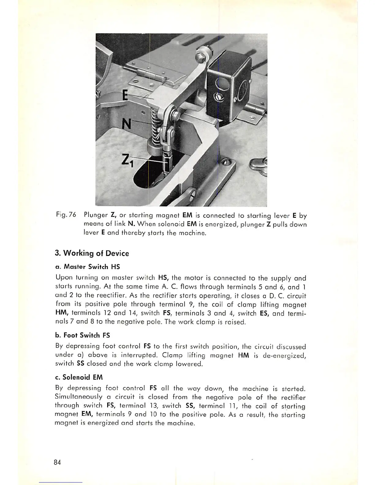
76 Plunger Z, or starting magnet
EM
is connected to starting lever E by
means of link N. When solenoid
EM
is energized, plunger Z pulls down
lever E and thereby storts the machine.
3. Working of Device
a.
Master
Switch
HS
Upon turning on master
switch
HS,
the motor is connected to the supply and
storts running. At the some time A. C. flows through terminals 5
and
6,
and
1
and 2 to the reectifier. As the rectifier starts operating, it closes a
D.
C. circuit
from
its positive pole through terminal 9, the coil of clomp lifting magnet
HM, terminals 12 and 14, switch FS, terminals 3
and
4, switch ES,
and
termi
nals 7 and 8 to the negative pole. The work clamp is raised.
b.
Foot
Switch
FS
By
depressing foot control
FS
to the first
switch
position, the circuit discussed
under a) above is interrupted. Clamp
lifting
magnet
HM
is de-energized,
switch SS closed and the work clamp lowered.
c.
Solenoid
EM
By
depressing foot control
FS
all the way down, the
machine
is started.
Simultaneously a circuit is closed from the negative pole of the rectifier
through
switch
FS,
terminal
13,
switch
SS,
terminal
11,
the coil of starting
magnet
EM,
terminals 9 and 10 to the positive pole. As a result, the starting
magnet
is
energized
and
starts
the
machine.
84