d.
Solenoid
HM
and
Switch
ES
Foot control
FS
is released. To ensure that clamp lifting magnet HM will re
main inoperative while sewing, the circuit discussed under a} above is inter
rupted by switch
ES
as long as the machine is in operation.
The two spark suppressors
FL,
which
are connected between terminals 8,
11
and 12, protect the contact points against excessive voltages. If, on special
request, the machine is equipped with sewlight transformer
LT,
the spark
suppressors
are
connected to terminols 1
and
2.
e.
Switch
SS
The function of switch SS is to interrupt the flow of current to machine
starting magnet
EM
for the short period of time it takes to lower the work
clamp onto the work. This prevents the machine from being started by quick
ly depressing foot control FS before the clomp has been lowered completely.
Switch SS closes the circuit to starting magnet
EM
only after the plunger in
clamp lifting magnet HM has dropped back (that is, when the clamp has been
lowered completely).
86
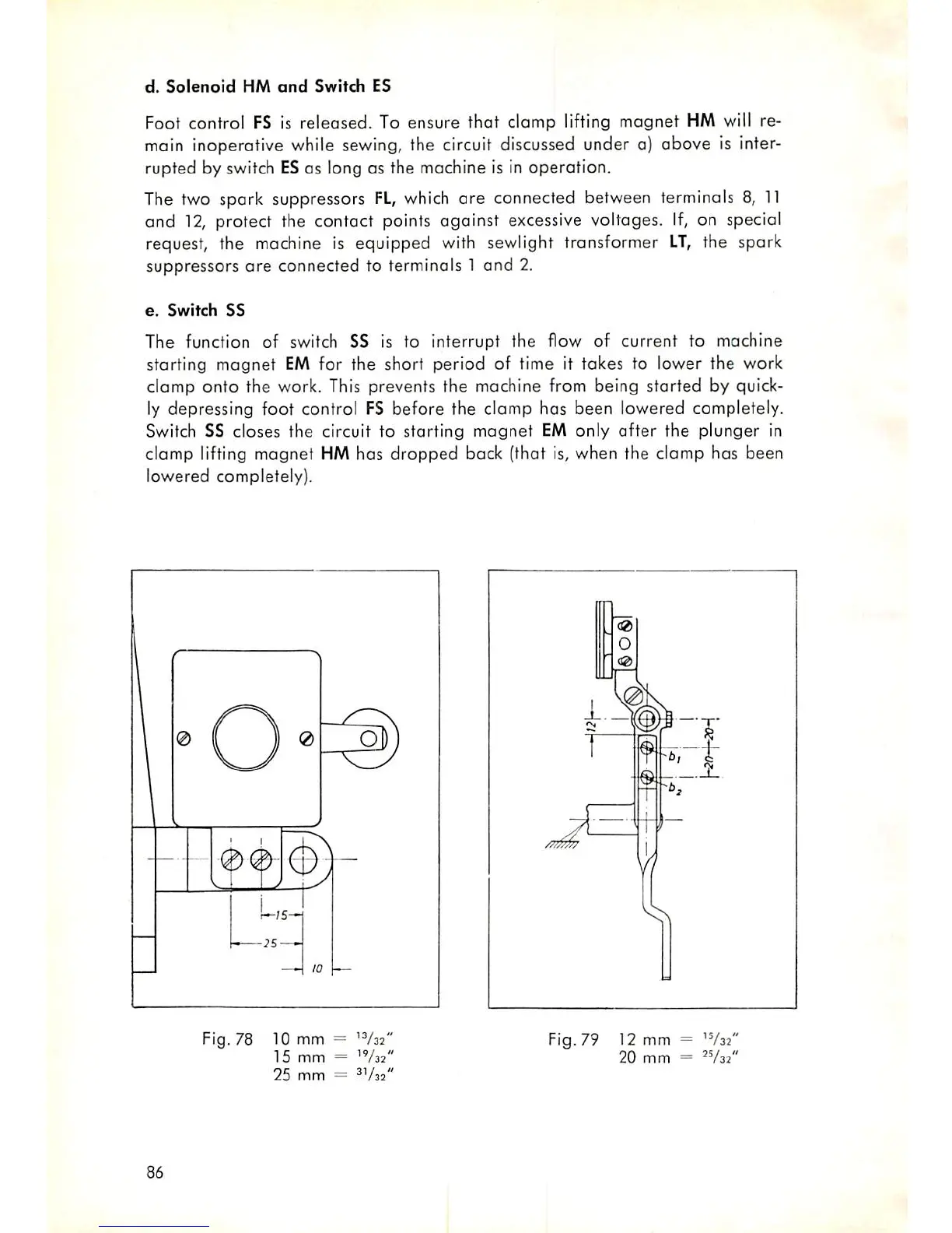
Fig. 78 10 mm =
'V32"
15
mm
=
"/as*
25
mm
=
Fig. 79 12 mm = 'V32'
20
mm
=
"/az''