Adjustment
20
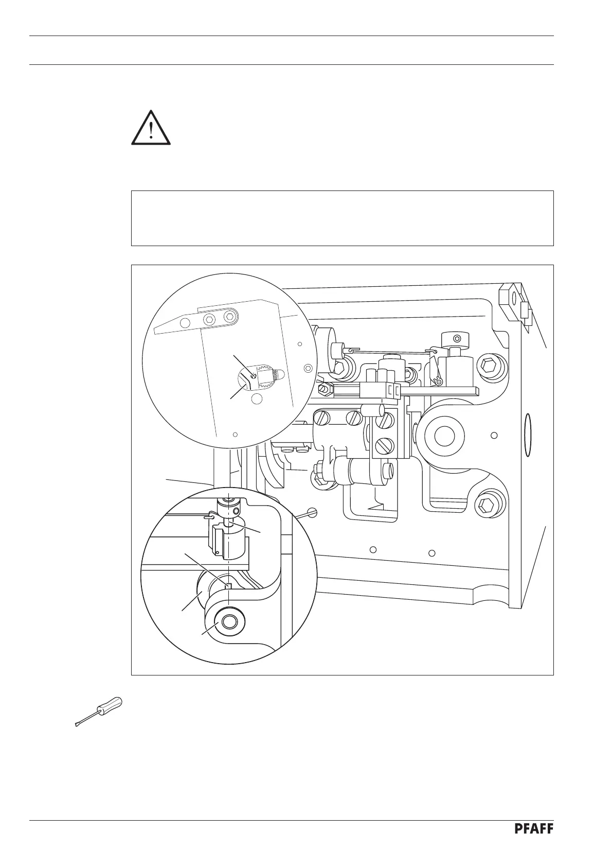
13.05 Adjusting the thread trimmer -900/52
Requirement
With the take-up lever at its bdc, projection 4 on the control cam 2 must be directly un-
derneath the cam follower 5.
Loosen screws 1 through the hole in the machine housing.
Set the take-up lever at b.d.c.
Turn control cam 2 according to Requirement.
Move control cam 2 down against bearing 3 and tighten the accessible screw 1.
Make the second screw 1 accessible and tighten it also.
●
●
●
●
●
Fig. 13 - 15
2
1
2
4
3
5
13
.05.01 Preadjusting the control cam
Please note that on all machines with thread trimmer -900/52 the stitch length
must be limited to 5.5 mm!

 Loading...


