Adjustment
25
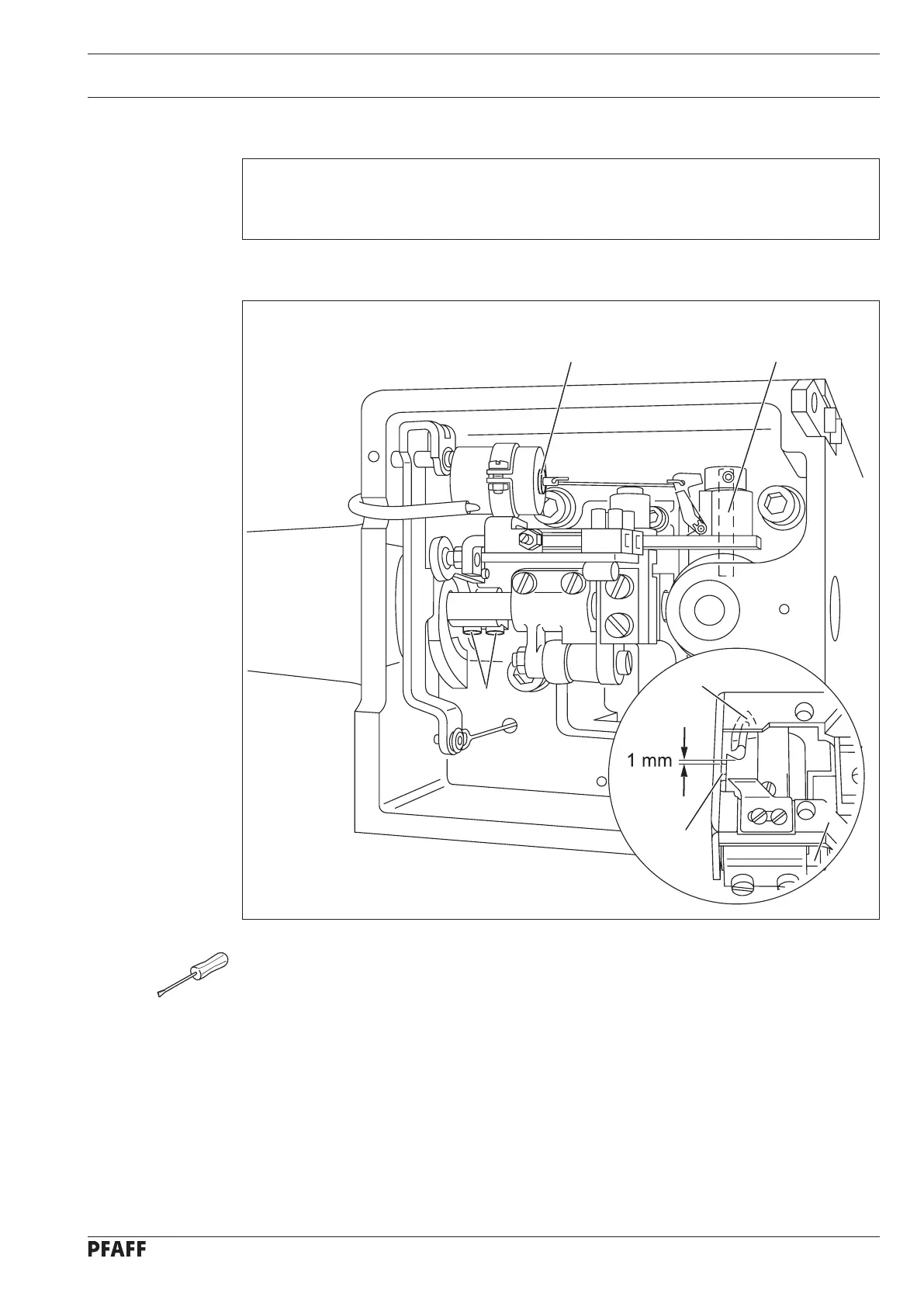
13.05.06 Front position of thread catcher
Requirement
With thread catcher 3 at its front position the back edge of the thread catcher cutout must be
1 mm beyond the front edge of bobbin case position stop 6.
Set the needle bar at b.d.c.
Operate solenoid core 1 so that control pin 2 drops into the cam track.
Turn the balance wheel in sewing direction to set thread catcher 3 at its front position.
Turn thread catcher 4 (screws 5) to set thread catcher 3 according to Requirement.
●
●
●
●
Fig. 13 - 20
1
2
5
3
6
4

 Loading...


