Adjustment
27
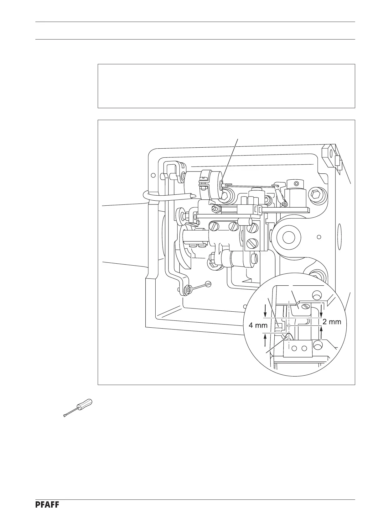
13.05.08 Control cam (final adjustment)
Requirement
When the end of hook gib 2 is 2 mm behind the centre of bobbin-case position finger 3, as
viewed in feeding direction, there must be a clearance of approx. 4 mm between catcher
point 4 and hook gib 2.
Set the needle bar at b.d.c.
Operate solenoid core 1 by hand.
Turn the balance wheel farther (sewing direction) until the end of hook gib 2, viewed in
sewing direction, is 2 mm behind the centre of bobbin case position finger 3.
Check according to requirement and re-adjust control cam if necessary, see Chapter
13.05.01 Control cam (preliminary adjustment).
●
●
●
●
Fig. 13 - 22
1
2
3
4
 Loading...


