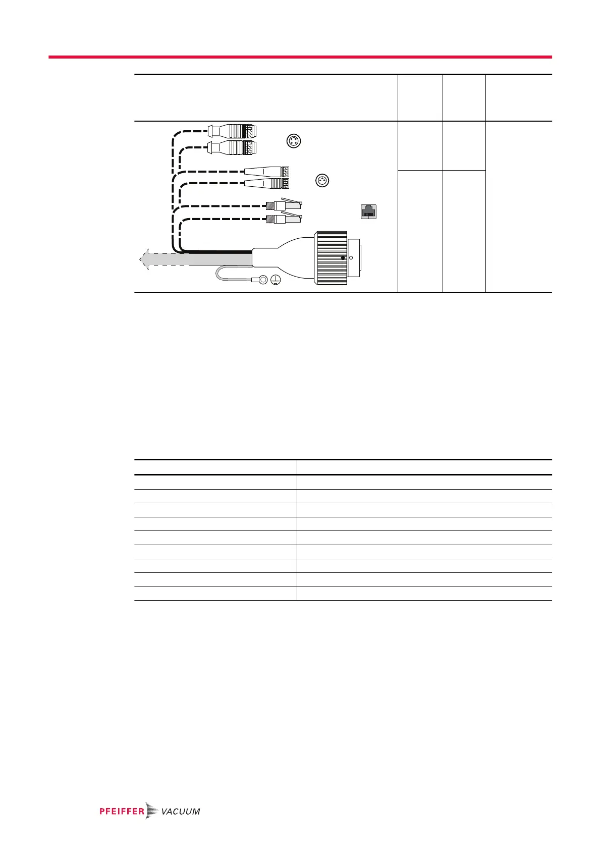
Connection cable Acces-
sory
connec-
tion
Acces-
sories
Current load,
max.
TCP 350
TMP
FAN/HEAT
VENT
A1
B1
A1
B1
4
4
1
1
2
3
3
A1
or
FAN/
HEAT
Air
cooling
or
Heating
I
max
≤ 200 mA
B1
or
VENT
only
Venting
valve
Tbl. 10: Connection cable TCP350 – turbopump with variants of the accessory connection
Connecting accessory devices
1. Observe the installation instructions in the operating instructions for the relevant accessory.
2. Use parameter [P:035] to configure the existing connections and control cables for the required
accessory.
–
Only FAN/HEAT is valid for A1.
3. When connecting a backing pump, use an adapter cable to connect the relay box to the "Remote"
output on the electronic drive unit.
4. If sealing gas is required, use a sealing gas throttle instead of a valve.
4.8 Connecting gauges
Measuring tubes Display [P:738]
APR 250/260 CMRx61
CMR 261/361 CMRx61, following manual selection
CMR 262/362 CMRx62, following manual selection
CMR 263/363 CMRx63, following manual selection
CMR 264/364 CMRx64, following manual selection
CMR 365 CMRx65, following manual selection
PCR 280 TP/PCR
PKR 251/261/360/361 PKR2xx
TPR 270/280/281 TP/PCR
Tbl. 11: Available types of gauges
Procedure
1. As required, connect a gauge to the "GAUGE" connection.
2. The corresponding connection cable is available as a Pfeiffer Vacuum accessory.
3. If needed, set parameter [P:738] to change display name of gauge.
Installation
24/56
 Loading...