[P:708]
D
B
C-D = Gas mode "0"
A-B = Gas mode "1"
A
C
P
max
P
f
N
f
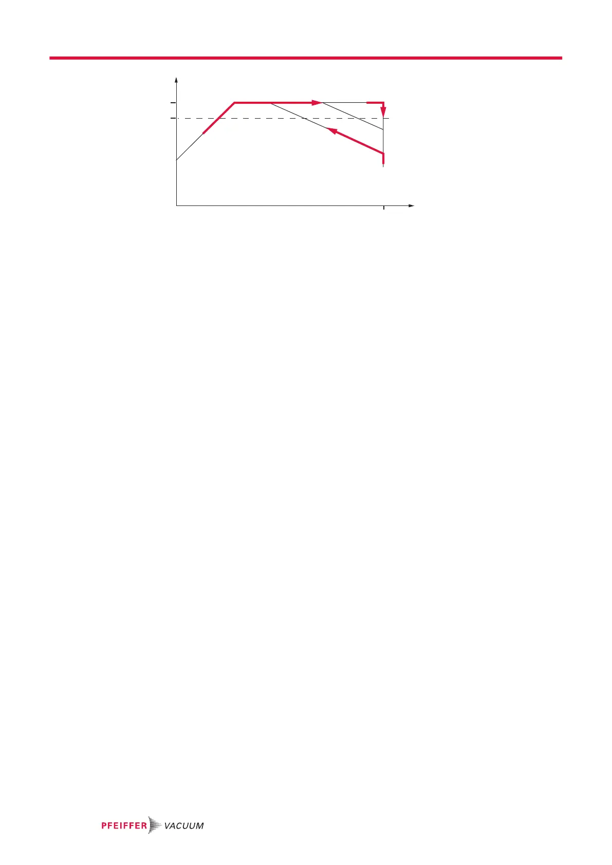
Fig. 11: Schematic diagram of power characteristics, example of heavy gases [P:027] = 0
P Power consumption f
N
Nominal rotation speed
f Rotation speed C-D Power characteristic in gas mode "0" (gases with molecular
mass > 39, e.g. Argon)
P
max
Maximum power con-
sumption
A-B Power characteristic in gas mode "1" (gases with molecular
mass ≤ 39)
Setting gas mode
1. Check the current gas mode set with parameter [P:027].
2. Set the parameter [P:027] to the required value.
3. If necessary, set a lower frequency in rotation speed setting mode in order to avoid rotation speed
fluctuations.
The turbopump runs up with maximum power consumption. When the nominal and/or set rotation speed
is reached, the electronic drive unit automatically switches over to the chosen power characteristic of
the selected gas mode. The increase in the power consumption initially compensates an increasing gas
throughput to keep the rotation speed of the turbopump constant. The turbopump heats up higher due
to the increasing gas friction. When the gas-type-dependent maximum power is exceeded, the rotation
speed of the turbopump is reduced by the electronic drive unit until a permissible balance between pow-
er and gas friction is achieved.
7.7.3 Run-up time
Turbopump run-up is time-monitored in the factory. There are various causes of prolonged run-up
times, for example:
●
Excessive gas throughput
●
Leak in system
●
Setpoint of the run-up time too low
Parameterizing run-up time
1. Activate the run-up time monitoring with parameter [P:004].
2. Adjust the run-up time with parameter [P:700].
3. Where applicable, eliminate any external and application-related causes, if there are extended
run-up times.
7.7.4 Setting rotation speed switchpoint
You can use the rotation speed switch point for the “Turbopump operational for the process” message.
Exceeding or falling below the active rotation speed switch point activates and/or deactivates the status
parameter [P:302] and the associated remote output:
Signal output at"REMOTE" connection pin 8:
●
DO1: high
●
Relay 1: active (pins 15, 16, 17)
Operation
40/56
 Loading...