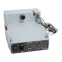
Connecting to external bus system
To connect to an external bus system, the Profibus DP, DeviceNet or Profinet interfaces
are possible as an option.
●
The field bus option cannot be retrofitted on the standard device.
●
For installed, alternative bus systems, the functionality of the RS-485 interface is limit-
ed.
TCP
TCP
D+
D-
USB/RS-485-converter
TIC 001/
RS 485
USB
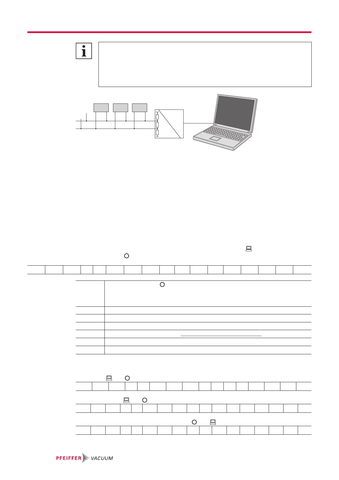
Fig. 9: Cross-linking of turbopumps via RS-485 interface
Connect the peripheral devices
The group address of the electronic drive unit is 988.
1. Install the devices according to the specification for RS-485 interfaces.
2. Connect all devices with RS-485 D+ and RS-485 D- to the bus.
3. Make sure that all devices connected to the bus have different RS-485 device addresses [P:797].
5.3 Pfeiffer Vacuum protocol for RS-485 interface
5.3.1 Telegram frame
The telegram frame of the Pfeiffer Vacuum protocol contains only ASCII code characters [32; 127], the
exception being the end character of the telegram C
R
. Basically, a master (e.g. a PC) sends a tele-
gram, which a slave (e.g. electronic drive unit or gauge) responds to.
a2 a1 a0 * 0 n2 n1 n0 l1 l0 dn ... d0 c2 c1 c0 C
R
a2 – a0 Unit address for slave
● Individual address of the unit ["001";"255"]
● Group address "9xx" for all identical units (no response)
● Global address "000" for all units on the bus (no response)
* Action according to telegram description
n2 – n0 Pfeiffer Vacuum parameter numbers
I1 – I0 Data length dn to d0
dn – d0 Data in the respective data type (see chapter “Data types”, page 29).
c2 – c0 Checksum (sum of ASCII values of cells a2 to d0) modulo 256
C
R
carriage return (ASCII 13)
5.3.2 Telegram description
Data query --> ?
a2 a1 a0 0 0 n2 n1 n0 0 2 = ? c2 c1 c0 c
R
Control command --> !
a2 a1 a0 1 0 n2 n1 n0 l1 l0 dn ... d0 c2 c1 c0 c
R
Data response / Control command understood -->
a2 a1 a0 1 0 n2 n1 n0 l1 l0 dn ... d0 c2 c1 c0 c
R
Interfaces
28/56
 Loading...