38 www.psterer.com
Drawings not to scale - for information only Size 3 | 3-S / Standard instructions wire screen / No. 040 371 001 (2014-05-08) i-01
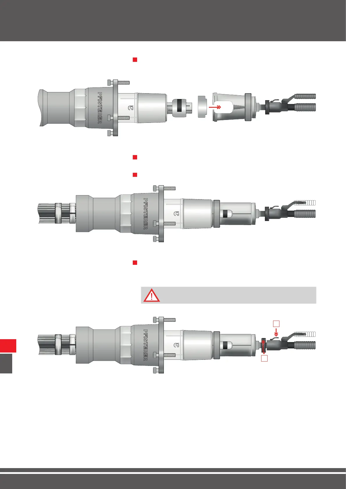
Place the pressure plate on the insert of the compression head and slide
the retaining ring of the compression head to the back.
7 1
Place the half-shells of the compression head behind the removal tools
and press together.
8 1
Slide the retaining ring forward.
9 1
Turn the knurled wheel [1] of the hydraulic compression tool to the right
until the pressure plate of the compression head lies rmly on the ten-
sion cone.
10 1
1
2
Dismantling / Removal
IX
Release the hydraulic compression tool before operating [2].