Revision: 3.0.3
4 Transducer Installation
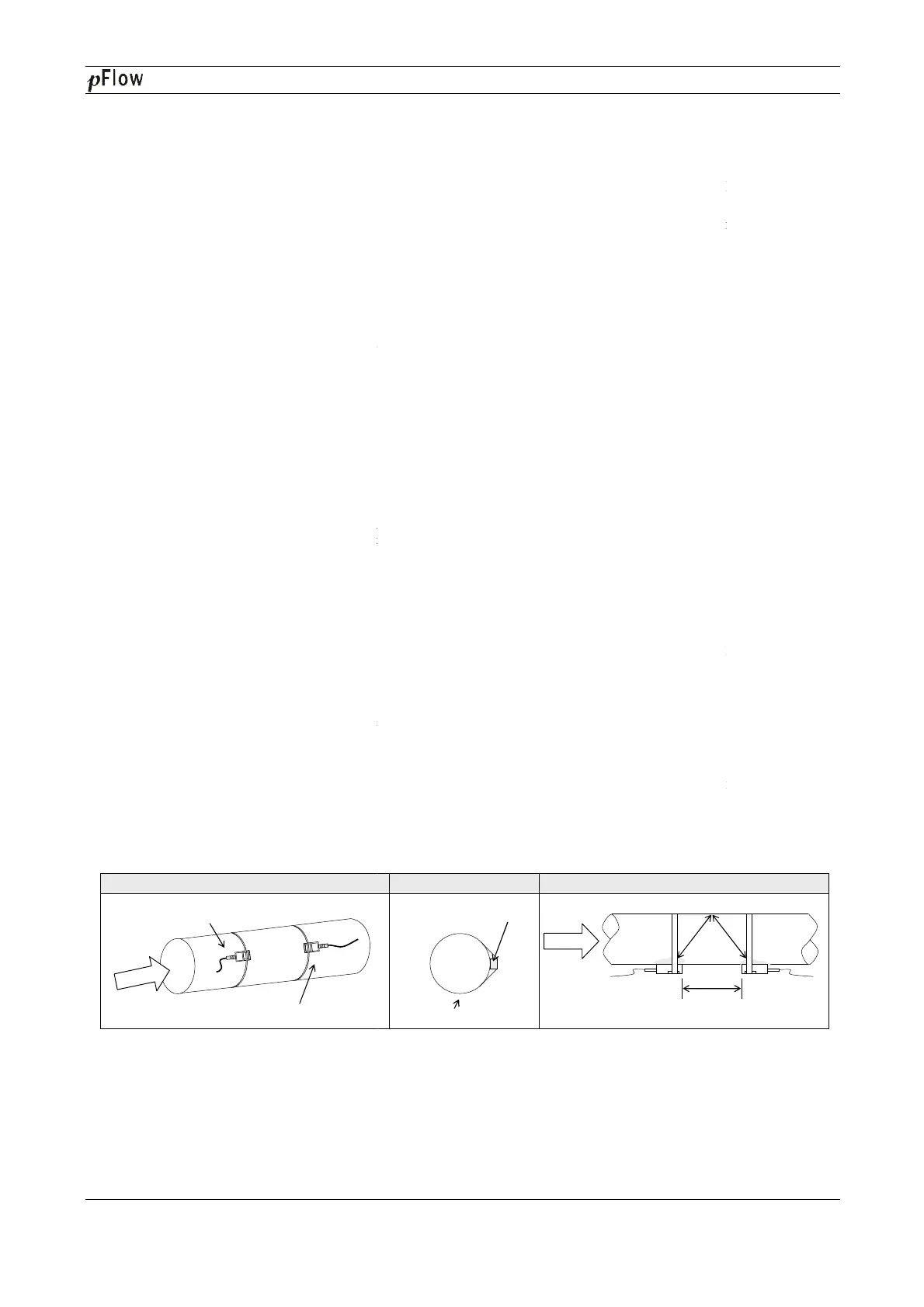
4.1 Installing the transducers
Before installing the transduce
rs, clean the pipe surface where the transducers are to be mounted. Remove any rust,
scale or loose paint and make a smooth surface. Choose a section of sound conducting pipe for installing the
transducers. Apply a wide ban
d of sonic coupling compound down
well as on the pipe surface,
ensure there are no air bubbles between the transducers and the pipe wall,
attach the transducers to the pipe with the straps provided and tighten them securely.
Note:
The
two transducers should be mounted at the pipe’s centerline on horizontal pipes.
Make sure that the transducer mounting direction is parallel with the flow.
During the installation, there should be no air bubbles or particles between the transducer and the
horizontal pipes, the transducers should be mounted in the 3 o’clock and 9 o’clock positions of the pipe section in
order to avoid any air bubbles inside the top portion of the pipe. (Refer to Transducer Mounting). If the
transducers cannot
be mounted horizontally symmetrically due to limitation of the local installation conditions, it
may be necessary to mount the transducers at a location where there is a guarantee
always full of liquid).
4.1.1 Transducer Spacing
After entering the required parameters, the spacing between the ENDS of the two transducers is considered as the
standard transducer spacing (Refer to Top View on transducer mounting methods). Check the data displayed in
Window M25 and space the transduce
4.1.2
Transducer Mounting Methods
Three
transducer mounting methods are available. They are respectively: V method, Z method
V method is primarily used on small diameter pipes (DN100
appli
cations where the V method cannot work due to poor signal or no signal detected. In addition, the Z method
generally works better on larger diameter pipes (over DN300mm, 12
The N method is an uncommonly used method.
4.1.3 V Method
The V method is considered as the standard method. It usually gives a more accurate reading and is used on pipe
diameters ranging from 25mm to 400mm (1
requires proper installation of the transducer
either side of the centerline.
Upstream Transducer
Flow
Side View
D116
Series Ultrasonic Flowmeter
rs, clean the pipe surface where the transducers are to be mounted. Remove any rust,
scale or loose paint and make a smooth surface. Choose a section of sound conducting pipe for installing the
d of sonic coupling compound down
the center of the face of each transducer as
ensure there are no air bubbles between the transducers and the pipe wall,
attach the transducers to the pipe with the straps provided and tighten them securely.
two transducers should be mounted at the pipe’s centerline on horizontal pipes.
Make sure that the transducer mounting direction is parallel with the flow.
During the installation, there should be no air bubbles or particles between the transducer and the
horizontal pipes, the transducers should be mounted in the 3 o’clock and 9 o’clock positions of the pipe section in
order to avoid any air bubbles inside the top portion of the pipe. (Refer to Transducer Mounting). If the
be mounted horizontally symmetrically due to limitation of the local installation conditions, it
may be necessary to mount the transducers at a location where there is a guarantee
d
full pipe condition (the pipe is
After entering the required parameters, the spacing between the ENDS of the two transducers is considered as the
standard transducer spacing (Refer to Top View on transducer mounting methods). Check the data displayed in
Transducer Mounting Methods
transducer mounting methods are available. They are respectively: V method, Z method
V method is primarily used on small diameter pipes (DN100
~300mm, 4〞~12〞
). The Z method is used in
cations where the V method cannot work due to poor signal or no signal detected. In addition, the Z method
generally works better on larger diameter pipes (over DN300mm, 12
〞) or cast iron pipes.
The N method is an uncommonly used method.
It is used on sma
ller diameter pipes (below DN50mm, 2
The V method is considered as the standard method. It usually gives a more accurate reading and is used on pipe
~16〞
) approximately. Also, it is convenient to use, but
requires proper installation of the transducer
s
, contact on the pipe at the pipe’s centerline and equal spacing on
Flow
Top ViewSection
Pipe Strap
Transducer
Series Ultrasonic Flowmeter
Page 15 of 53
rs, clean the pipe surface where the transducers are to be mounted. Remove any rust,
scale or loose paint and make a smooth surface. Choose a section of sound conducting pipe for installing the
the center of the face of each transducer as
ensure there are no air bubbles between the transducers and the pipe wall,
and then
pipe wall. On
horizontal pipes, the transducers should be mounted in the 3 o’clock and 9 o’clock positions of the pipe section in
order to avoid any air bubbles inside the top portion of the pipe. (Refer to Transducer Mounting). If the
be mounted horizontally symmetrically due to limitation of the local installation conditions, it
full pipe condition (the pipe is
After entering the required parameters, the spacing between the ENDS of the two transducers is considered as the
standard transducer spacing (Refer to Top View on transducer mounting methods). Check the data displayed in
N method. The
). The Z method is used in
cations where the V method cannot work due to poor signal or no signal detected. In addition, the Z method
ller diameter pipes (below DN50mm, 2
〞).
The V method is considered as the standard method. It usually gives a more accurate reading and is used on pipe
) approximately. Also, it is convenient to use, but
still
, contact on the pipe at the pipe’s centerline and equal spacing on