Revision: 3.0.3
1.3 Powering on
As soon as the Flowmeter is switched on, the self
error code will display on the screen (Refer
automatically according to the last input parameters.
If the installation is accomplished when system is switched on, gain adjustment can be mo
After S1, S2, S3, S4 are displayed on the upper left corner of the screen, the system will activate the normal
measurement condition automatically. It is indicated by code
If it is the fir
st time to use or install on a new site, the customer need to input the new installation site
The system will default to the last window settings and automatically display the
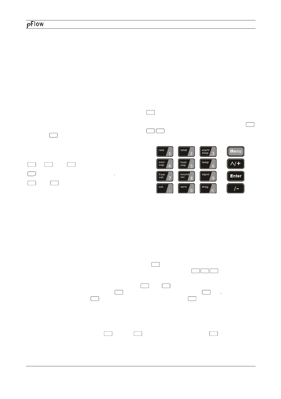
1.4 Keypad Functions
This keypad is dual function keypad:
1. When separately pressed, is shortcut function,
referring to "2. Quickly set menu
2. Press
and Number key, is Menu key,
referring to"6.Menu Window Description".
Follow these guidelines when using the Flowmeter
keypad (Refer to Keypad Figure):
~ And To input numbers.
Backspace or delete characters to the left.
And
Return to the last menu or to open
the next menu. Acts as "+" and "-"
entering numbers.
1.5 Keypad Operation
The flow meter adopts the window software design to consolidate or subdivide all of the parameters entered, the
instrument setup and measurement result displays into more than 100 independent windows. The operator ca
input parameters, modify settings or display measurement results by "visiting" a specific window. These windows
are arranged by 2-
digit serial numbers (including "+" sign) from 00~99, then to +0, +1, etc. Each window serial
number, or so-called window ID
code, has a defined meaning. For example, Window M11 indicates the parameter
input for pipe outside diameter, while Window M25 indicates the mounting spacing between the transducers, etc.
(Refer –
Windows Display Explanations).
The keypad shortcut to visi
t a specific window is to press the
ID code. For example, to input or check the pipe outside diameter, just press the
ID code 11.
Another method to visit a particular window is to press
the current window ID code is M02, press
Window M00; then, press the
key to back Window M01, and press the
M02.
Win
dows are separated into three types: (1) Data Type, such as M11, M12; (2) Option Type, such as M14; (3)
Pure Display Type, such as M01, M00.
You can check the corresponding parameters by visiting the Data Type Windows. If you want to m
parameters, input the digits and press
Menu
0 9
●
<
^
^
^
Enter
D116
Series Ultrasonic Flowmeter
As soon as the Flowmeter is switched on, the self
-
diagnosis program will start to run. If any error is detected, a
error code will display on the screen (Refer
- Error Diagnoses). After that self-
diagnosis, the system will run
automatically according to the last input parameters.
If the installation is accomplished when system is switched on, gain adjustment can be mo
After S1, S2, S3, S4 are displayed on the upper left corner of the screen, the system will activate the normal
measurement condition automatically. It is indicated by code
"*R"
on the upper left corner of the screen.
st time to use or install on a new site, the customer need to input the new installation site
The system will default to the last window settings and automatically display the
m
1. When separately pressed, is shortcut function,
";
and Number key, is Menu key,
Follow these guidelines when using the Flowmeter
Backspace or delete characters to the left.
Return to the last menu or to open
Select a menu. Press this key fir
menu numbers and then enter the selected menu. For
example, to input a pipe outside diameter, press
keys, where "11"
display the parameter for pipe outside diameter.
The flow meter adopts the window software design to consolidate or subdivide all of the parameters entered, the
instrument setup and measurement result displays into more than 100 independent windows. The operator ca
input parameters, modify settings or display measurement results by "visiting" a specific window. These windows
digit serial numbers (including "+" sign) from 00~99, then to +0, +1, etc. Each window serial
code, has a defined meaning. For example, Window M11 indicates the parameter
input for pipe outside diameter, while Window M25 indicates the mounting spacing between the transducers, etc.
Windows Display Explanations).
t a specific window is to press the
key at any time, then input the 2
ID code. For example, to input or check the pipe outside diameter, just press the
Another method to visit a particular window is to press
and
keys to scroll the screen. For example, if
key to enter Window M01, press the
key to back Window M01, and press the
key again to enter Window
dows are separated into three types: (1) Data Type, such as M11, M12; (2) Option Type, such as M14; (3)
You can check the corresponding parameters by visiting the Data Type Windows. If you want to m
or press first, input the digits then press
Menu
1 1
Menu
Menu
1 1
^
^
^ ^
^
Enter Enter
Series Ultrasonic Flowmeter
Page 9 of 53
diagnosis program will start to run. If any error is detected, a
n
diagnosis, the system will run
After S1, S2, S3, S4 are displayed on the upper left corner of the screen, the system will activate the normal
on the upper left corner of the screen.
st time to use or install on a new site, the customer need to input the new installation site
parameters.
Select a menu. Press this key fir
st, input two
menu numbers and then enter the selected menu. For
example, to input a pipe outside diameter, press
display the parameter for pipe outside diameter.
The flow meter adopts the window software design to consolidate or subdivide all of the parameters entered, the
instrument setup and measurement result displays into more than 100 independent windows. The operator ca
n
input parameters, modify settings or display measurement results by "visiting" a specific window. These windows
digit serial numbers (including "+" sign) from 00~99, then to +0, +1, etc. Each window serial
code, has a defined meaning. For example, Window M11 indicates the parameter
input for pipe outside diameter, while Window M25 indicates the mounting spacing between the transducers, etc.
key at any time, then input the 2
-digit window
keys to scroll the screen. For example, if
key again to enter Window
dows are separated into three types: (1) Data Type, such as M11, M12; (2) Option Type, such as M14; (3)
You can check the corresponding parameters by visiting the Data Type Windows. If you want to m
odify the
Menu