Revision: 3.0.3
5.5 Frequency Output
The Flowmeter is provided with a frequency output transmitter function. The high or low frequency output
displayed indicates the high or low flow rate reading. The user can res
as his requirements.
For example: if a pipe flow range is 0~3000
configuration is as follows:
In Window M68 (low limit frequency output flow value
In Window M69 (high limit frequency output flow value), input 3000;
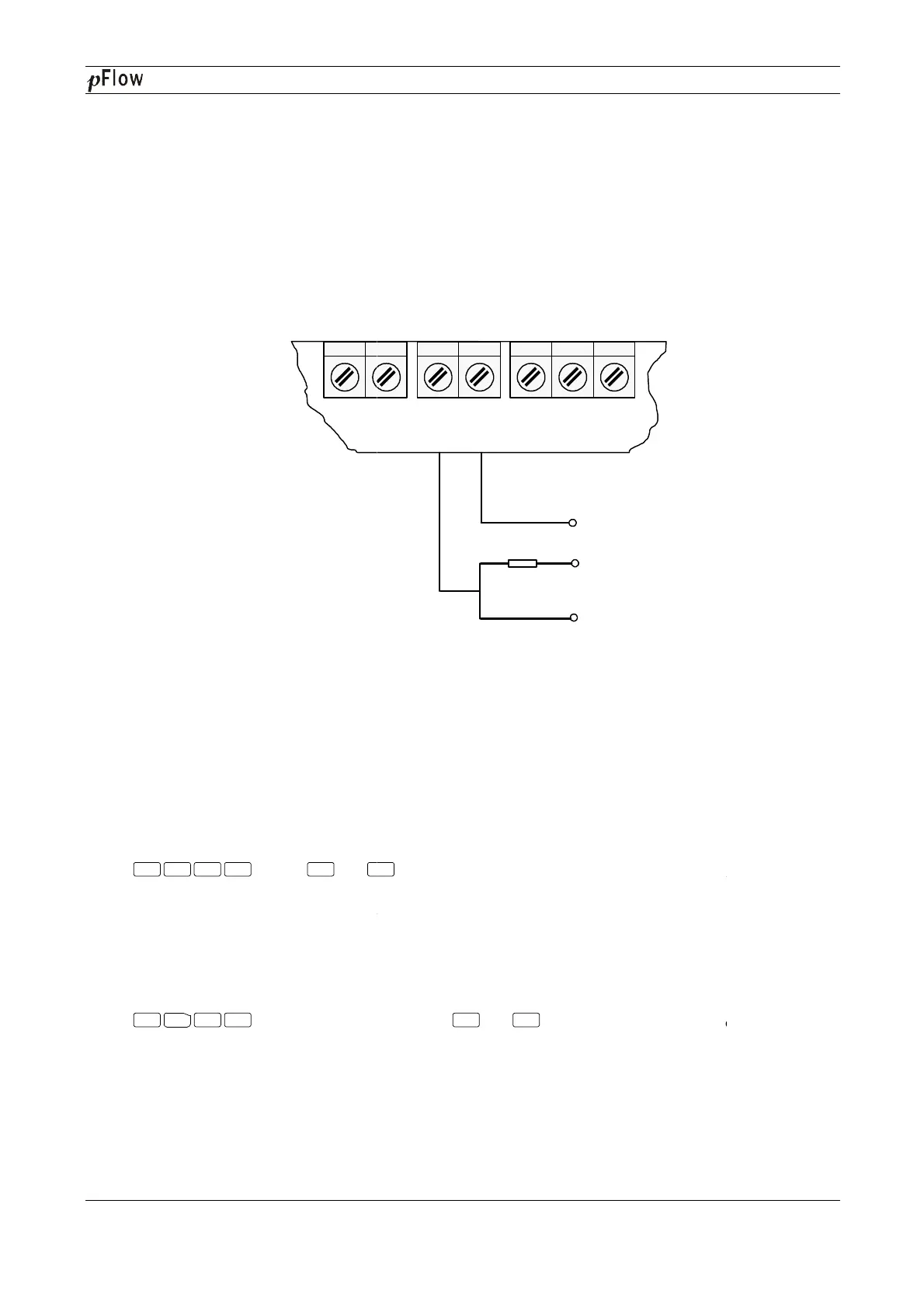
Typical OCT Output wiring diagram as below:
5.6 4~20mA Current Loop
Processing a current loop output exceeding an
with multiple output modes such as flow
"Windows Display Explanations".
In Window M56, enter a 4mA flow rate
in Window M57. For example, if the flow range in a specific pipe is 0
1000 in Window M57.
Calibrating and testing the current loop is performed
Press , move or
readings, connect an ammeter to test the current loop output and calculate the difference. Calibrate it if the
difference is within tolerance.
If the difference is without tolerance, refer to the "
calibrate the current loop.
Check the present current loop output in Window M59 as it changes along with change in flow.
5.7
Recover the Factory Default
Press
factory default.
Menu 5 8 Enter
^
Menu
3
7 Enter
D116
Series Ultrasonic Flowmeter
The Flowmeter is provided with a frequency output transmitter function. The high or low frequency output
displayed indicates the high or low flow rate reading. The user can res
et the frequency output as well as flow rate
3
/h, the relative frequency output required is 0~5
In Window M68 (low limit frequency output flow value
), input 0;
In Window M69 (high limit frequency output flow value), input 3000;
Typical OCT Output wiring diagram as below:
OCT Output Wiring Diagram
Verification (Optional)
Processing a current loop output exceeding an
accuracy of
0.1%, the flowmeter is programmable and configurable
or fluid velocity
. Select in Window M55. For details, please refer to
value. Enter the 20mA flow rate
in Window M57. For example, if the flow range in a specific pipe is 0
~1000m3
/h, enter 0 in Window M56 and
Calibrating and testing the current loop is performed
in Window M58. Complete the steps as follows:
to display "0mA", "4mA", "8mA", "12mA","
readings, connect an ammeter to test the current loop output and calculate the difference. Calibrate it if the
If the difference is without tolerance, refer to the "
Analog Output
Check the present current loop output in Window M59 as it changes along with change in flow.
Recover the Factory Default
press or
key to choose"Reset"keys to recover the
OCT+ OCT-
OCT OUT
COM
E UP+ UP-
TRANS
5~10K 1/4w
Vcc
Sig
^
^
^
Series Ultrasonic Flowmeter
Page 20 of 53
The Flowmeter is provided with a frequency output transmitter function. The high or low frequency output
et the frequency output as well as flow rate
0.1%, the flowmeter is programmable and configurable
. Select in Window M55. For details, please refer to
value
/h, enter 0 in Window M56 and
in Window M58. Complete the steps as follows:
", "20mA"
readings, connect an ammeter to test the current loop output and calculate the difference. Calibrate it if the
" to
key to choose"Reset"keys to recover the