Do you have a question about the PFlow Industries D116 and is the answer not in the manual?
Important safety warning regarding potential injury from device use.
Cautionary note about potential damage to the flow meter from improper handling.
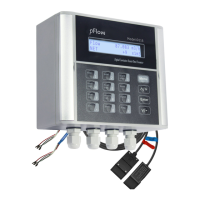
Describes the main unit of the ultrasonic flowmeter, including its interface.
Details the sensors used for measuring flow in the pipe.
Lists included items like pipe straps and coupling compound.
Refers to accompanying materials like the instruction manual and packing list.
Guide on checking for damage and preparing for transmitter mounting.
Instructions for electrical connections, including power supply and transducer wiring.
Details on extending the sensor cable length for flexible installation.
Procedure for starting the flowmeter and initial self-diagnosis.
Explanation of the dual-function keys and their operational modes.
Guidance on navigating menus and inputting data using the keypad.
Overview of different display windows and their assigned serial numbers or IDs.
Explains how specific keys access predefined measurement displays.
Step-by-step guide demonstrating parameter entry for common measurement scenarios.
Procedures for mounting transducers, including cleaning, compound application, and methods.
Details on V, Z, and N methods for transducer installation based on pipe size and conditions.
Steps to verify correct transducer installation and ensure signal integrity.
How to interpret system status indicators like "*R", "G", or "I" on the display.
Procedure to calibrate the zero point for accurate low-flow measurements.
Explanation of the scale factor and its use in adjusting measurement results.
How to lock and unlock the instrument to prevent unauthorized parameter changes.
Configuration of frequency output settings for flow rate indication.
Testing and calibration of the 4-20mA analog output signal.
Detailed steps for calibrating the 4-20mA current loop output to ensure accuracy.
Information about the Electronic Serial Number (ESN) for instrument identification.
A comprehensive list of window IDs and their corresponding parameter descriptions.
Detailed explanations of various display screens and the data they present.
Adjustment of the damping factor to stabilize flow display readings.
Procedure for setting the zero point when the fluid is in a static state.
Details on locking the instrument to prevent unauthorized parameter modification.
Displays the current output value and guidance for re-calibration if needed.
Controls for the LCD backlight, including options for always on or off.
Configuration of output trigger sources for the OCT signal.
Selection of units for energy measurement (GJ, Kcal, KWh, etc.).
Monitoring and interpreting signal strength and Q value for optimal installation.
Viewing the history of instrument power on/off events and associated flow rates.
A reference table listing error codes, their causes, and recommended solutions.
Common issues and their resolutions for troubleshooting the flowmeter.
General introduction to the ultrasonic flowmeter and its technology.
Highlights the key advantages and distinctive features of the D116 model.
Technical details including performance, function, and physical specifications of the flowmeter.
General information on networking capabilities and communication interfaces.
Instructions for establishing a direct communication link using RS-485.
Details on the communication protocols and their application for data exchange.
Introduction to the W211 insertion type transducers and their installation capabilities.
Guidelines for selecting optimal points for installing insertion transducers.
Procedures for measuring and setting transducer spacing for insertion types.
Details the Z method for mounting W211 insertion transducers based on application.
Explains the function of the RTD module for temperature input in energy measurements.
Wiring diagram and methods for connecting PT1000 temperature sensors to the RTD module.
Describes the formulas and methods used for calculating energy consumption.
Outlines two methods for calibrating the RTD module's temperature readings.
Visual guide showing the RTD module before and after installation on the circuit board.
| Brand | PFlow Industries |
|---|---|
| Model | D116 |
| Category | Measuring Instruments |
| Language | English |