Revision: 3.0.3
1
Transmitter Installation and Connection
1.1 Inspection
prior to Transmitter Installation
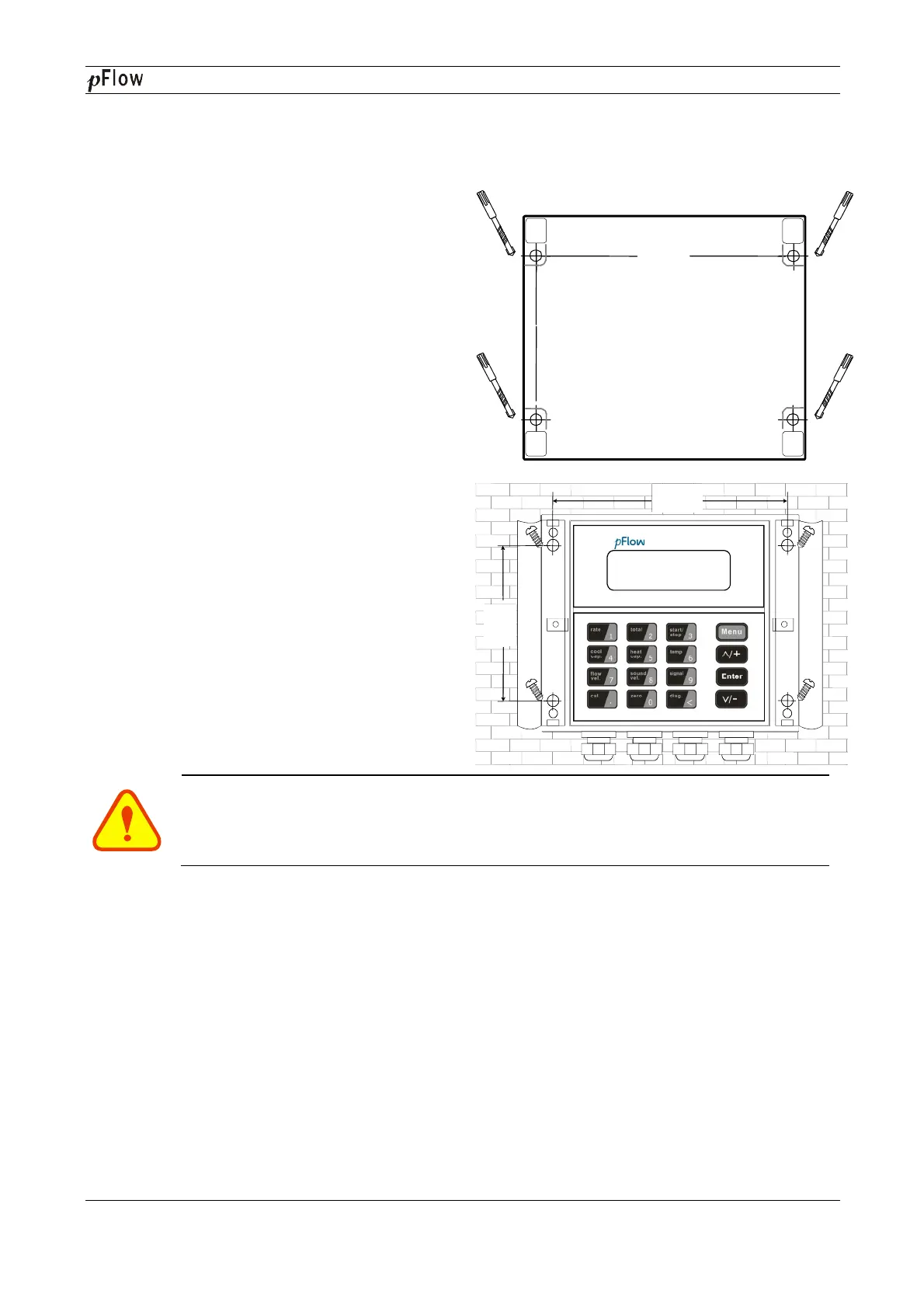
You will find a "Position Drawing"
Please
use it as a template in the place that
going to install the Flowmeter. Then drill 4 installing
holes at the screws position shown on
the 5.0mm drill.
Take out the enclosed screws and plastic bushings.
Insert
the plastic bushings into the installing holes. Put
the flowmeter to the position and screw
Attention
When installing please ensure the front cover
D116
Series Ultrasonic Flowmeter
Transmitter Installation and Connection
prior to Transmitter Installation
use it as a template in the place that
you are
going to install the Flowmeter. Then drill 4 installing
Take out the enclosed screws and plastic bushings.
the plastic bushings into the installing holes. Put
When installing please ensure the front cover
is secure and will not fall open.
86 mm
135 mm
5.32lnch
3.39lnch
Position drawing
1. Place this template on the wall and drill 4
holes of 5mm diameter & 40mm deep.
2. Insert a plastic bushing into each of the 4
holes.
3. Screw 4 pcsPA 4
×
screws through the transmitter enclosure
base and attach it to the wall.
4. Tighten the screws to secure to the
enclosure on the wall.
MODEL DCT1188
Digital Correlation Transit -Time
135mm
5.32lnch
86mm
3.39lnch
·
MODEL: D116G
Digital Correlation Transit -Time Flowmeter
Series Ultrasonic Flowmeter
Page 6 of 53
1. Place this template on the wall and drill 4
holes of 5mm diameter & 40mm deep.
2. Insert a plastic bushing into each of the 4
screws through the transmitter enclosure
4. Tighten the screws to secure to the