Revision: 3.0.3
10 Appendix2-W211
10.1 Overview
W211
type insertion transducers can be installed into metal pipelines via an isolation ball valve (installation into
pipelines of plastic or other materials may require an optional mounting seat). The maximum pipe diameter in
which insertion transducers can be
length (9m standard) normally can be extended to as long as 100m.
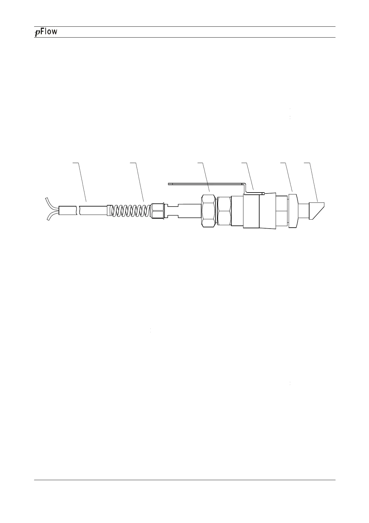
Figure 1 shows a diagram of the W211
Insertion Transducer. The insertion transducer is attached to its mounting
base
(which is welded to the pipe section at the measurement point) via a ball valve. When the transducer is
removed, pipe fluids can be contained by shutting off the ball valve. Therefore, installation and extraction of the
transducer can be performed without
relieving pipeline pressure. An O
safety while installing or operating the transducer.
Construction Drawing of W
1. Cable
2. Connector
10.2
Measurement Point Selection
To guarantee highly accurate measurement results, it is necessary to select an appropriate measurement point
before installing the transducer. For examples of measuring point selection, see the relat
10.3
Determining Transducer Spacing & Transducer Installation
The mounting space of insertion transducer is the center
(please refer to Menu 25). After enter the right parameter, plea
mm)
Mounting method:
1.
Drilling at the measuring point, the diameter of the drilling hole is 24mm. Before drilling, please make the
hole center of transducer mounting base aim at the drilling hole center, and
vertically.
(When the flowmeter need to be hot
interruption,please refer to the Sitelab’
equipment.)
2. Close the ball
valve and screw it tightly on the mounting base.
3.
Twist off the locknut and loose the lock ring, pull the transducer into the joint nut, and then screw up the
joint nut on the ball valve.
1 2
D116
Series Ultrasonic Flowmeter
ransducer
type insertion transducers can be installed into metal pipelines via an isolation ball valve (installation into
pipelines of plastic or other materials may require an optional mounting seat). The maximum pipe diameter in
1200. Fluid temperature range: +10℃~+80oC.
length (9m standard) normally can be extended to as long as 100m.
Insertion Transducer. The insertion transducer is attached to its mounting
(which is welded to the pipe section at the measurement point) via a ball valve. When the transducer is
removed, pipe fluids can be contained by shutting off the ball valve. Therefore, installation and extraction of the
relieving pipeline pressure. An O
-
ring seal and joint nut guarantee user
safety while installing or operating the transducer.
Construction Drawing of W
211 Transducer
3. Locknut
4. Ball value
5.
6. Sensor
Measurement Point Selection
To guarantee highly accurate measurement results, it is necessary to select an appropriate measurement point
before installing the transducer. For examples of measuring point selection, see the relat
ed section in the manual.
Determining Transducer Spacing & Transducer Installation
The mounting space of insertion transducer is the center
-to-
center hole distance between the two transducers
(please refer to Menu 25). After enter the right parameter, plea
se check the mounting space in Menu 25. (unit:
Drilling at the measuring point, the diameter of the drilling hole is 24mm. Before drilling, please make the
hole center of transducer mounting base aim at the drilling hole center, and
(When the flowmeter need to be hot
-
tapped into the pipe under pressure without flow
operation construction of DDK electric Hot-
valve and screw it tightly on the mounting base.
Twist off the locknut and loose the lock ring, pull the transducer into the joint nut, and then screw up the
3 4 5
Series Ultrasonic Flowmeter
Page 47 of 53
type insertion transducers can be installed into metal pipelines via an isolation ball valve (installation into
pipelines of plastic or other materials may require an optional mounting seat). The maximum pipe diameter in
Insertion Transducer. The insertion transducer is attached to its mounting
(which is welded to the pipe section at the measurement point) via a ball valve. When the transducer is
removed, pipe fluids can be contained by shutting off the ball valve. Therefore, installation and extraction of the
ring seal and joint nut guarantee user
To guarantee highly accurate measurement results, it is necessary to select an appropriate measurement point
ed section in the manual.
center hole distance between the two transducers
se check the mounting space in Menu 25. (unit:
Drilling at the measuring point, the diameter of the drilling hole is 24mm. Before drilling, please make the
tapped into the pipe under pressure without flow
Twist off the locknut and loose the lock ring, pull the transducer into the joint nut, and then screw up the
6