Revision: 3.0.3
4.
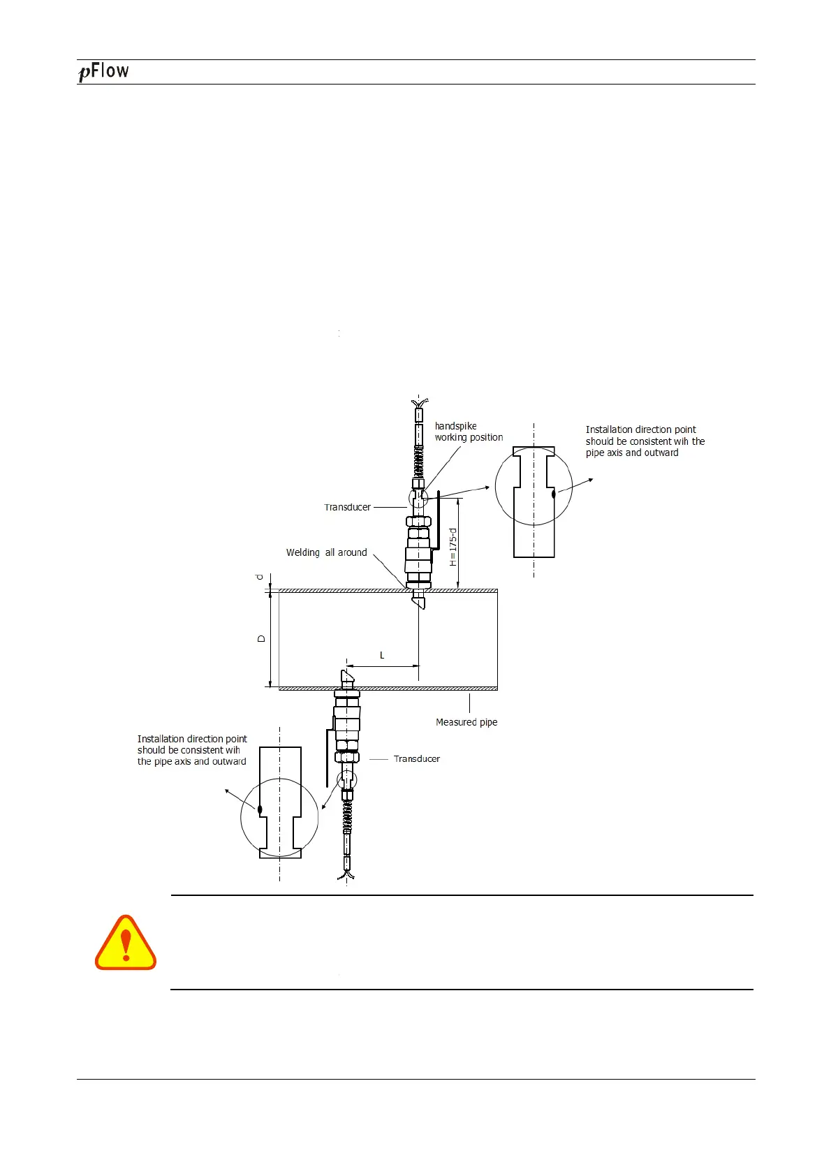
Open the ball valve and insert the transducer, measure the dimension
front end surface of handspike position to meet the following formula:
H=175-d
In this formula:
H is Mounting height (mm);
175 is Transducer length (mm);
d is Pipe wall thickness(mm);
5. Attach the lock ring to the j
oint nut by fitting its pinhole in the locating pin, then tighten the screw slightly
and turn the orientation handle until it points at the middle position between the two transducers and its axes
matches the axes of the pipeline. Finally, tighten the lock
joint nut.
6.
Connect the transducer cables to the corresponding upstream/downstream (upstream=red, downstream=blue)
terminal ends.
7.
Please refer to the following installation diagram:
Important
For
horizontal pipelines, transducers must be fixed on the sides of the pipe (i.e. at the 3 and 9
o’clock position of the pipe) to prevent signal attenuation caused by sediment on the bottom of
the pipe or air bubbles and air pockets in the top of the pipe.
D116
Series Ultrasonic Flowmeter
Open the ball valve and insert the transducer, measure the dimension
from the outer surface of the pipe to the
front end surface of handspike position to meet the following formula:
oint nut by fitting its pinhole in the locating pin, then tighten the screw slightly
and turn the orientation handle until it points at the middle position between the two transducers and its axes
matches the axes of the pipeline. Finally, tighten the lock
ing screw and screw the locating sleeve onto the
Connect the transducer cables to the corresponding upstream/downstream (upstream=red, downstream=blue)
Please refer to the following installation diagram:
horizontal pipelines, transducers must be fixed on the sides of the pipe (i.e. at the 3 and 9
o’clock position of the pipe) to prevent signal attenuation caused by sediment on the bottom of
the pipe or air bubbles and air pockets in the top of the pipe.
Series Ultrasonic Flowmeter
Page 48 of 53
from the outer surface of the pipe to the
oint nut by fitting its pinhole in the locating pin, then tighten the screw slightly
and turn the orientation handle until it points at the middle position between the two transducers and its axes
ing screw and screw the locating sleeve onto the
Connect the transducer cables to the corresponding upstream/downstream (upstream=red, downstream=blue)
horizontal pipelines, transducers must be fixed on the sides of the pipe (i.e. at the 3 and 9
o’clock position of the pipe) to prevent signal attenuation caused by sediment on the bottom of