Section 7 | Seies | 1570-100 | Rev | 2022-03-01 | e-mail csd@pow.com
Section 7 | Mechanical Overview
www.pflow.com
P 414 352 9000
F 414 352 9002
6720 N. Teutonia Ave.
Milwaukee, WI 53209
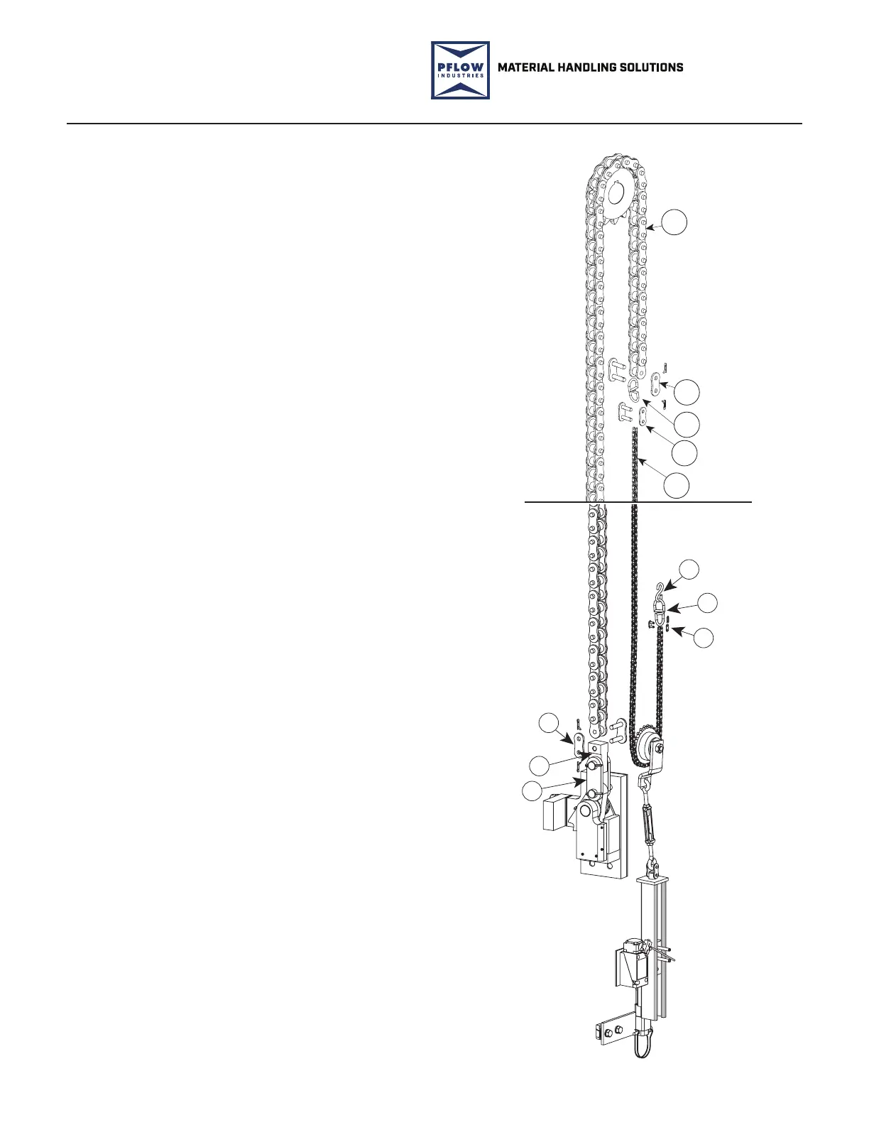
Lift Chains
Inside each column, one end of the
li chain connects to a safety cam
assembly which is bolted to the
carriage upright.
The li chain goes up and over the
li sprocket at the top of the column
drivebase assembly, then proceeds
downward through the chain guard
(chain tube), and connects to the
smaller tensioner chain.
The tensioner chain then travels
around the small chain tensioner
sprocket and back up to the carriage to
fasten to a bolt on the stando on the
carriage upright.
The tensioner sprocket is spring-loaded
by the chain tensioner which maintains
tension on the chain/tensioner
combination. If the li chain is pulled
too tight or becomes slack, the chain
tensioner limit switch is activated to
shut o power to the VRC.
The chain tensioner is adjusted
at a turnbuckle on the chain
tensioner assembly.
See Figure 7-6.
Li Chain System
Figure 7-6
2
3
4
5
1
10308-0002.SMG
PFL-200115-3
3
4
2
7
8
6
1. it Cain
2. aste in
3. Swivel
. aste in
5. ensione Cain
. S-oo
7. ole
. Saet Cam in
 Loading...