Seies | 1570-100 | Rev | 2022-03-01 | e-mail csd@pow.com Section 7 | 5
Section 7 | Mechanical Overview
www.pflow.com
P 414 352 9000
F 414 352 9002
6720 N. Teutonia Ave.
Milwaukee, WI 53209
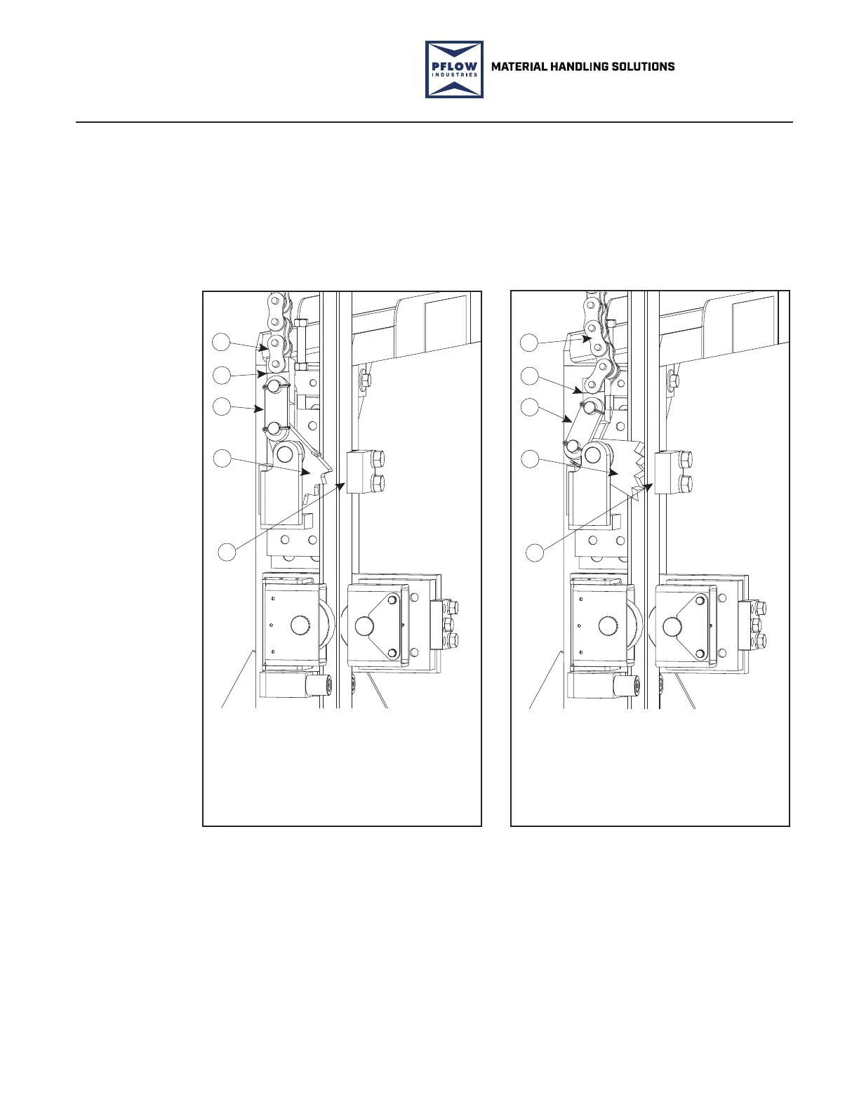
Each safety cam assembly has teeth and a shoe. The shoe (bolted to the safety cam
assembly base) ts around the outside of the column guide angle track while the steel
safety cam is pivoted on the safety cam mounting block. It is torsion spring-loaded. If
the li chain breaks or becomes slack, the safety cam pivots into a jam position with
the column guide angle to stop the carriage from falling. The safety cam shoe on the
outside of the guide angle track helps wedge the safety cam teeth. See Figure 7-7 and
Figure 7-8.
Safety Cam
Function
1. Lift Chain
2. Toggle
3. Connecting Link
4. Safety Cam
5. Safety Cam Shoe
18613-0100.SMG
PFL-200115
3
2
1
4
5
1. Lift Chain
2. Toggle
3. Connecting Link
4. Safety Cam
5. Safety Cam Shoe
18613-0100.SMG
PFL-200115-1
3
2
1
4
5
Safety Cam Disengaged
Figure 7-7
Safety Cam Engaged
Figure 7-8
 Loading...