Seies | 1570-000 | Rev | 2022-03-01 | e-mail csd@pow.com Section | 1
Section 8 | Electrical Overview
www.pflow.com
P 414 352 9000
F 414 352 9002
6720 N. Teutonia Ave.
Milwaukee, WI 53209
All electrical devices are connected
individually to the main control panel.
The main control panel contains a fused
transformer, motor starter, relays, etc.
A motor overload and current sensor
is provided to protect the motor from
excessive current draw.
One (1) push-button station is normally
supplied for each level. ASME B20.1
code requires that the push-button
stations be remotely located and unable
to be activated by someone standing on
the carriage. Each push-button station
contains Send to “x” push-buttons and
an emergency stop (E-stop).
The Send to “x” push-buttons are
momentary contact. This means the
operator can press and release the
Send to “x” push-button and the carriage
will travel to the selected level. The
operator does not need to hold the
Send to “x” push-button for the carriage
to continue moving. When pressed, the emergency stop prevents the carriage
from moving. The emergency stop must be pulled out before carriage movement
can be initiated again.
As required by NEC code, the main disconnect switch must be lockable and
located within line of sight of the control panel and no more than 6' 6" (1,981 m)
o the oor.
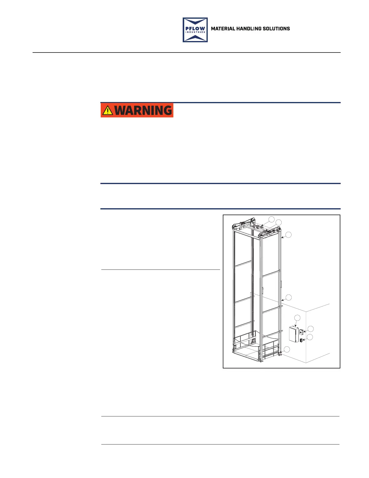
1. Drivebase Assembly
2. Drive Chain Limit Switch
3. Overtravel Limit Switch
4. Second Level Limit Switch
5. Main Control Panel
6. Disconnect Switch
7. First Level
Push-Button Station
8. Lift Chain Tensioner
Limit Switch
11
2
3
4
5
6
7
8
10308-0002.SMG
PFL-180905
Electrical Components Figure 8-1
The following is a standard description of the electrical wiring of an F series VRC.
This does not include any specics on options available or ordered (e.g., gates,
DeckLocks, photo eyes). A copy of the electrical schematic can be found in the
control panel and the shipping packet originally included in the parts crate.
Falling hazard! Make sure all safety devices are in place and operable before using
the equipment. If any safety device is missing or inoperable, immediately remove the
equipment from service.
Per ASME B20, all gates or doors accessing the li area must be electro-mechanically
interlocked. This requires electrical contacts to prevent the li from operating if a gate
is open when the carriage is at the level and mechanical locks to lock the gate until the
carriage is at that level.
Dierent gate interlock types and styles are supplied depending upon the gate type
and site conditions. Standard gate styles incorporate one to four electrical components
per gate.
Electrical
Overview
Main Control
Panel
Push-Button
Stations
Main Disconnect
Switch
NOTE
 Loading...