Section 7 | 2 Seies | 1570-100 | Rev | 2022-03-01 | e-mail csd@pow.com
Section 7 | Mechanical Overview
www.pflow.com
P 414 352 9000
F 414 352 9002
6720 N. Teutonia Ave.
Milwaukee, WI 53209
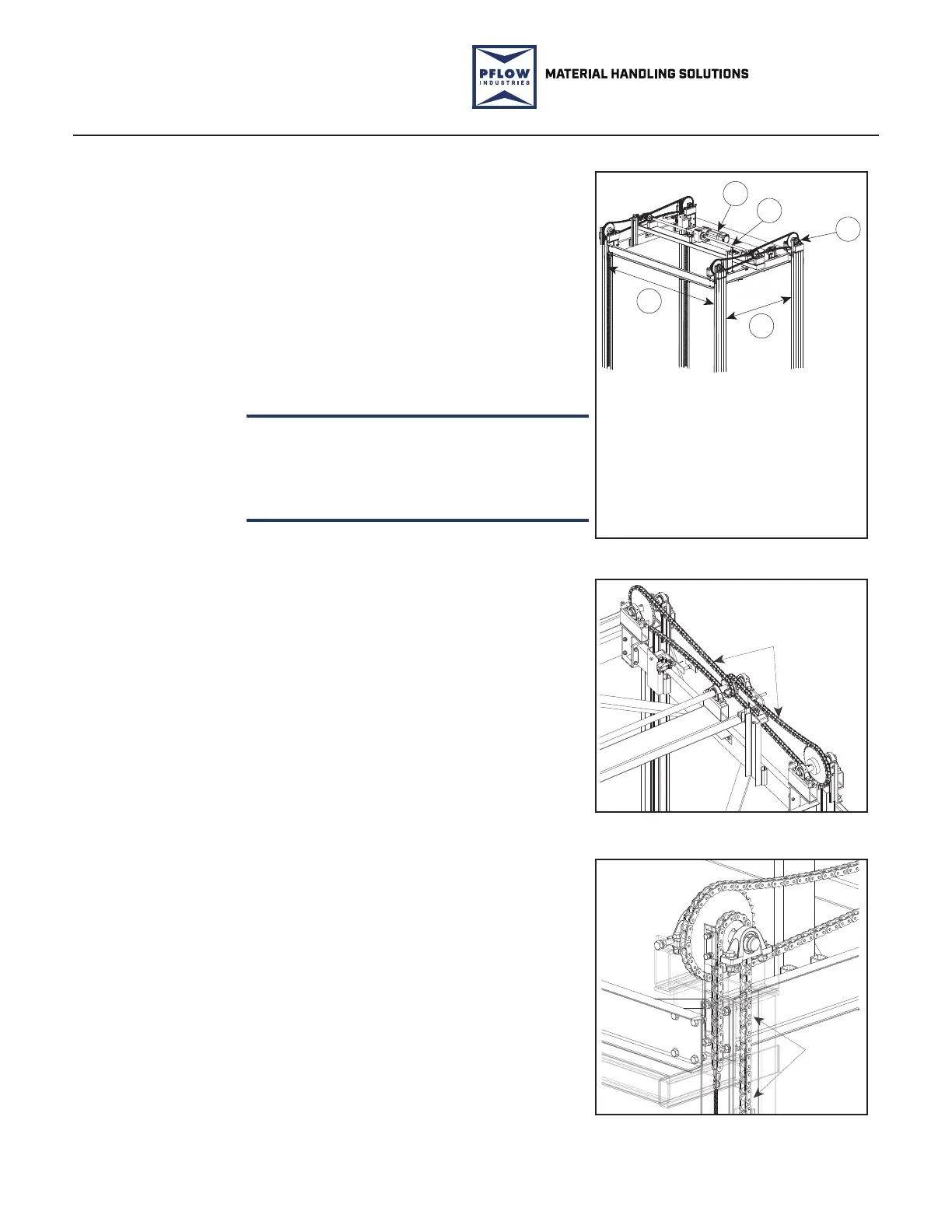
The drivebase assembly consists of a motor,
brake, gearmotor reducer (commonly
referred to as a gear motor assembly), li
sprockets, a drive sha, bearings, and a
support structure. Roller chains connect the
drive sprocket on the sha of the drivebase
assembly to the larger driven sprocket on the
corner assemblies on top of each column.
Roller li chains connect to safety cams
and tensioner chains and chain tensioners
complete the components. See Figure 7-2,
Figure 7-3, and Figure 7-4.
This VRC uses special high strength chain.
Do not use standard ANSI roller chain or
connecting links as a replacement. Contact
PFlow Industries, Inc. Customer Support
Department for the required chain specification.
Drivebase
Assembly
1. Motor/Brake/Reducer
Assembly
2. Driveshaft
3. Corner Chain
Sprocket Assembly
4. Length (column to column)
5. Width (guide angle to
guide angle)
11
3
4
2
5
10308-0002.SMG
PFL-180904-1
Drivebase Assembly
Figure 7-2
NOTICE
Drive Chain
10308-0002.SMG
PFL-180718-2
Drive Chain
Figure 7-3
Lift
Chain
10308-0002.SMG
PFL-2161-1
Li Chain
Figure 7-4
 Loading...