Seies | 1570-100 | Rev | 2022-03-01 | e-mail csd@pow.com Section 7 | 7
Section 7 | Mechanical Overview
www.pflow.com
P 414 352 9000
F 414 352 9002
6720 N. Teutonia Ave.
Milwaukee, WI 53209
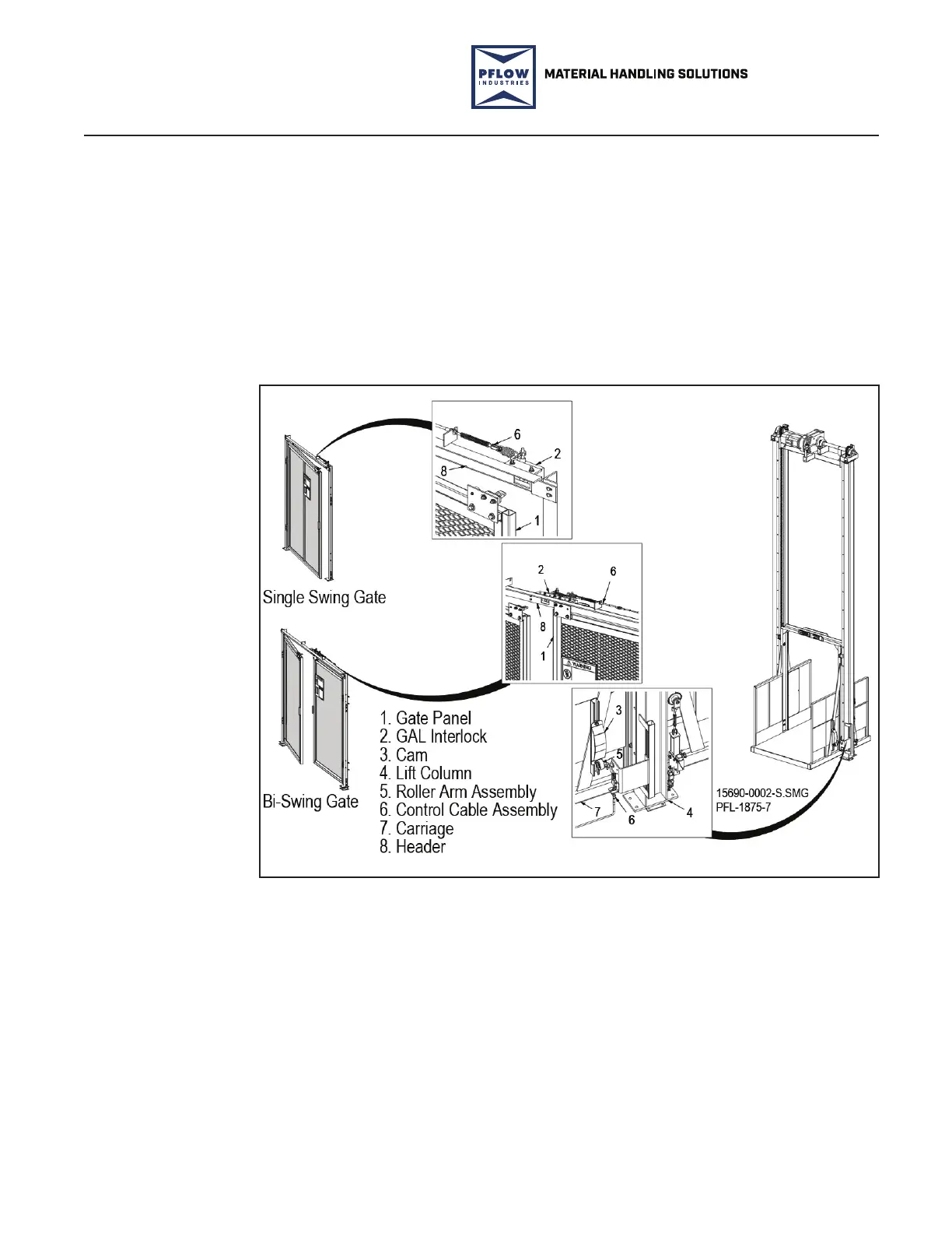
A safety gate assembly or door is provided at each level opening accessing in the
li area. All gates and/or doors accessing the li area are electromechanically
interlocked. When a gate or door is open the interlock prevents movement of
the carriage away from the respective level. When the carriage is not present at
a level, opening the gate or door is prevented by the mechanical interlock. See
Figure 7-10.
PFlow Industries, Inc. oers various styles of interlocks depending upon the gate
type and application.
The parts section of this manual contains views with part numbers.
Gate Assemblies
Swing Gate Interlock Examples
Figure 7-10
 Loading...