28 | P a g e
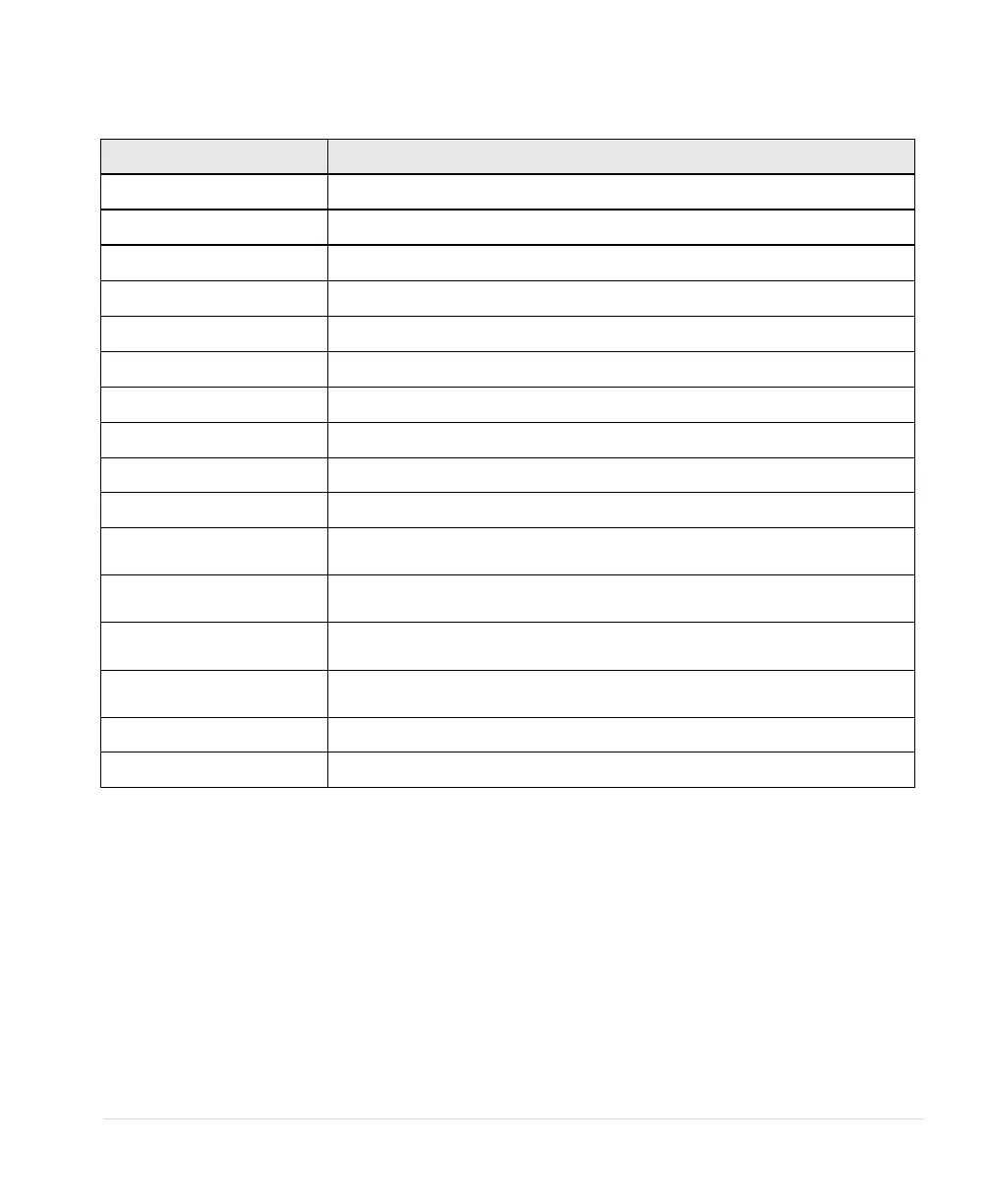
Table 11 – Measured Values
DESCRIPTION OF MEASURED VALUE
Three-phase currents on the output
Output measured in horse power
Output measured in kilowatts
Power factor of the motor load
ON/OFF status of the remote switch circuits AUX1 and AUX2
Displays the product model number
Measures the 0-5 VDC analog control voltage between Control Terminals
for 0-5VDC input.
Measures 4-20 mA analog control current on I_1 Control Terminals for
analog current input.
Measures 4-20 mA analog control current on I_2 Control Terminals for
analog current input.
Displays a timer that counts down the time left to start when the drive is
in a time delay due to a fault condition.