66 | P a g e
Figure 35 - Lead/Lag Schematic
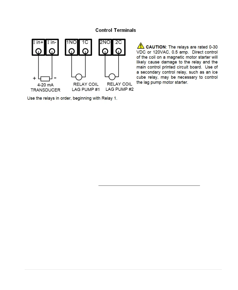
7.6 Duplex / Multiplex Control
When any analog CP system configuration is selected, the CONSTANT PRESSURE and LEAD/LAG
menus are available. Up to two additional VFDs can be controlled through the relays. When the
parameter NUMBER LAG PUMPS is greater than 0, all two relays will convert to control of lead/lag or
duplex/multiplex constant pressure. In addition, the parameter DUPLEX CYCLE TIME must be greater
than 0 for Multiplex control to be active.
When operating in Multiplex Control, the main VFD will assume the role of Master, and all auxiliary
VFDs controlled through the relays are known as Slaves. The Master and Slave VFDs will operate in
constant pressure mode.
If the Master VFD senses that system pressure cannot be maintained, it will call for a Slave VFD by
closing a relay on the control terminal. SD Series drives can control up to two auxiliary VFDs.
In Multiplex control, the Master VFD might not always be the drive that is operating. The point of a
multiplex system is to rotate the use of each available VFD. This is done so that a single drive or pump
does not degrade at a faster rate than other drives or pumps in that system. The Master VFD will decide
when to stage or de-stage a VFD. The first pump to be staged in, and the last pump to be de-staged, is
called the Primary VFD.
Multiplex Setup
System configuration must be set to one of the CP modes when using multiplex control. See Section
6.5, System Configuration for details. Multiplex control is enabled when NUMBER LAG PUMPS is
greater than 0, and DUPLEX CYCLE TIME is greater than 0.
Programming Steps: