67 | P a g e
1. Use the keypad to navigate to the Main Menu item, CHANGE PARAMETER VALUES, then to
sub-menu LEAD LAG PUMP PARAMETERS. Find the parameter NUMBER LAG PUMPS
and use the arrow keys to set the number of auxiliary drives in the system.
2. Navigate to CONSTANT PRESSURE PARAMETERS and find the parameter DUPLEX
CYCLE TIME and use the arrow keys to set how often the Primary drive position will change.
3. If necessary, adjust the remaining Lead/Lag parameters after reading the following description
of their functions, or after operating conditions dictate.
In Multiplex control, the Master VFD will utilize the Lead/Lag Parameters and logic similar to lead/lag
control in order to decide when to turn on/off a VFD. More detail on the logic behind these decisions will
be given in a later section.
It is not recommended to run an auxiliary pump directly from the Master VFD. The Master rotates which
unit is the Primary, which could result in a single auxiliary pump operating across-the-line at 60 Hz in a
bang-bang control system. The Primary Auxiliary Pump could turn on/off resulting in the system
pressure oscillating from (psi SETPOINT – STAGE PSI LAG) to (psi SETPOINT + DESTAGE PSI
LAG).
The Master VFD stages in VFDs in a different order depending on which VFD is the Primary. When the
Master VFD is not the Primary, it will ALWAYS be the second drive to be staged in.
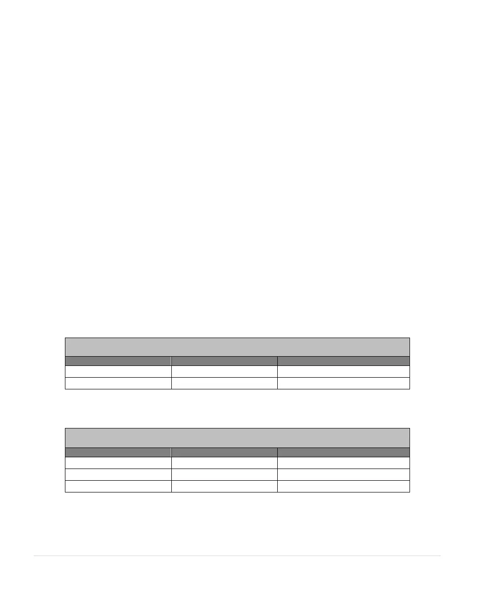
Table 19 and Table 20 below will illustrate the order of the VFDs to be staged or de-staged for different
values of NUMBER LAG PUMPS.
The Primary drive position will rotate based on the parameter DUPLEX CYCLE TIME.
Table 19 - Master + 1 Slave VFD