72 | P a g e
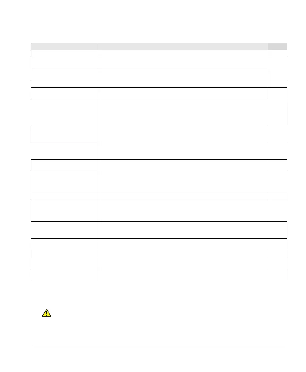
Table 21 – Fault Codes
Check for short circuit on output lines and load. Contact factory
Internal temperature of the drive exceeded safe limits. Check fans and ventilation
openings for obstruction. Reduce ambient temperature.
Sudden and severe regenerative power under high line voltage conditions may result in
bus overvoltage. Check line voltage or increase ramp up and ramp down times.
DC bus voltage did not reach normal level. Possible failure of input diode.
Input voltage has exceeded a level for safe operation. Reduce input voltage. General
purpose buck/boost transformers are compatible with 1LH Series drives.
Output current has exceeded the value set for OVERCURRENT LIMT in OPERATING
PARAMETERS menu. Check status of motor load. If output current limit is increased,
make sure it is within the limit of the motor nameplate. Automatic restarts are set by
RESTART DELAY 1 and RESTARTS CUR OVL in the AUTO RESTART
PARAMETERS menu.
Motor current unbalance has exceeded the limit set in CURRENT UNBALANC under
CHANGE PARAMETER VALUES menu. Check motor load for normal operation, or
increase current unbalance limit.
Real power in kW consumed by the motor load has fallen below the limit set in
MINIMUM POWER under CHANGE PARAMETER VALUES menu. Commonly used to
detect dry well condition.
Motor current has fallen below the value set in UNDERCURRENT LIM Commonly used
to detect dry well condition.
Indicates a large and sudden overcurrent event on the output module. Check the motor
circuit for faults. Sudden changes in the load may also have occurred such as the
closing of a relay that results in an across-the-line start of a motor. Never install relays in
the motor circuit.
Input voltage has fallen below a level for safe operation of the drive.
A fault between an output line and earth has been detected. Immediately disconnect
input power and check output lines with a megger to verify a fault. Nuisance trip is a
possibility. Sensitivity of fault detection can be adjusted by the Operating Parameter
GND FAULT DETECT. See Table 14 for details.
Indicates open circuit. 4-20mA analog signal is not present on Control Terminals I_1 and
I_2. This could indicate failure of the 4-20mA sensor or that the cables from the sensors
have been disconnected.
Indicates closed circuit. Check for short circuit between lines. Check the polarity of the
wires on I_1+ and I_1- .
Broken Pipe fault. Indicates the possibility of a broken pipe.
Switch connected to AUX1 input has opened. Drive will remain off until fault is cleared.
No auto restart allowed. See AUX1 SELECT in Table 17.
Switch connected to AUX2 input has opened. Drive will remain off until fault is cleared.
No auto restart allowed. See AUX2 SELECT in Table 17
P = Fault may be related to an adjustable parameter. Always check the value of the parameter to eliminate nuisance
tripping.
1 = Drive has shut down due to a potentially dangerous condition. Drive will remain OFF until input power is cycled
OFF/ON. Use caution if the drive is restarted.
2 = WARNING: Auto restart allowed for this fault. Motor may restart automatically without warning after a fault
when operating conditions permit. Make certain input power is disconnected before servicing the unit or its
connected loads.