Mechanical Instructions
EN 9LC7.2E LB 4.
4.3.3 Side I/O Panel
Refer to next figure for details.
1. Unplug connector [1].
2. Remove screw [2] and remove the entire module. It hinges
on the right side.
When defective, replace the whole unit.
Figure 4-5 Side I/O module
4.3.4 IR/LED Panel
Refer to next figure for details.
1. Release clips [1] and remove the board.
2. Unplug connector [2].
When defective, replace the whole unit.
Figure 4-6 IR/LED panel
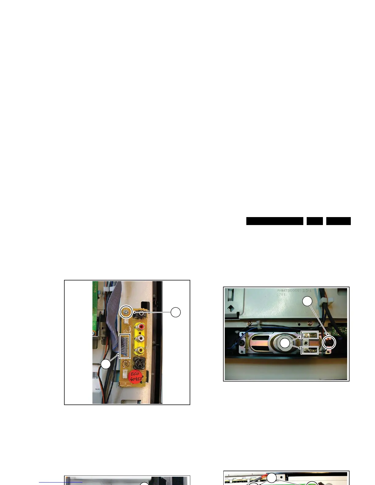
4.3.5 Speakers
Refer to next figure for details.
1. Unplug connectors [1].
2. Remove screw [2].
3. Lift out the speaker.
When defective, replace the speaker.
Figure 4-7 Speakers
4.3.6 LCD Interface Board
Refer to next figure for details.
1. Unplug connector [1].
2. Unplug the LVDS connectors [2]. Be careful as they are
very fragile.
3. Remove the screws [3] and take the panel out. It hinges at
the bottom side.
Figure 4-8 LCD interface board
H_17170_026.eps
220507
1
2
H_17170_027.eps
040607
1
2
H_17170_028.eps
220507
1
2
H_17170_029.eps
220507
3
3
1
2