Circuit Descriptions
EN 33LC9.3L LA 7.
2010-Mar-26
7.4 HDMI
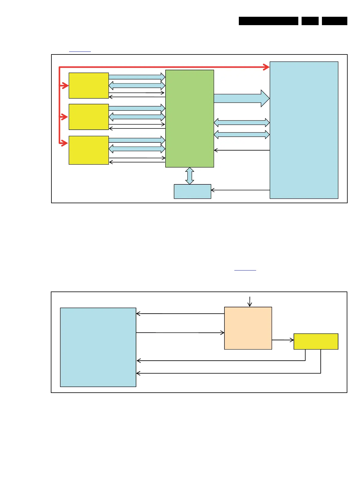
Refer to Figure 7-6 for the HDMI architecture.
Figure 7-6 HDMI architecture
Below find an explanation of the signals that are used:
• DDC: EDID information is read through the I
2
C lines and is
used for the HDCP authentication process as well
• CEC: connected to MT5392 and all HDMI input ports
directly
• EDID_WC: used to disable the write protection pin of the
EEPROM; when updating the EEPROM, pull this pin LOW
• TMDS: signal that contains video and audio
• HOTPLG: to initiate the source device for EDID reading
and HDCP authentication
• 5V: to indicate the presence of the source device for the
acknowledgement of the MT5392.
7.5 USB
Refer to Figure 7-7 for the USB architecture.
Figure 7-7 USB architecture
Below find an explanation of the signals that are used:
•USB_OC:
– normal operation signal level is “HIGH” (logic “1”)
– when the 5V supply to the USB device exceeds a
current limit of 700 mA, the RT9715HGS will pull the
signal level to “LOW” state (logic “0”), which will restart
the set
– if the die temperature exceeds 120 degrees C, the
signal will be “LOW” (logic “0”), which will restart the set
• USB_PWR_EN: to enable or disable the USB power switch
RT9715HGS; to enable, this signal must be set to logic “0”
• USB_DM, USB_DP: USB differential signal.
18970_205_100325.eps
100325
MT5392
HDMI
Connector 1
HDMI
Connector 2
HDMI
Connector
side
ADV3002
TMDS
DDC
TMDS
DDC
TMDS
DDC
5 V
HOTPLUG
HOTPLUG
5 V
5 V
HOTPLUG
TMDS
DDC
Local I
2
C
CEC
Reset
EDID E2PROM
EDID I
2
C
EDID_WC
18970_206_100325.eps
100325
MT5392
GPIO 1
GPIO 2
USB_PWE
USB_OC
RT9715HGS
USB DM
USB DP
VIN
VOUT
USB
connector
5V
EN_
FLG_
+5V_SW
USB _DM
USB _DP
1D03
7D00
7400