Do you have a question about the Philips FW C717 and is the answer not in the manual?
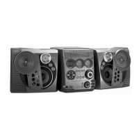
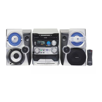
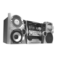
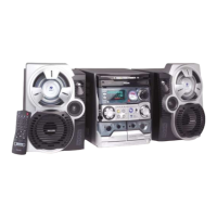
| Speaker Type | 3-way Bass Reflex Speaker System |
|---|---|
| Disc Playback | CD, CD-R, CD-RW, MP3-CD |
| Bluetooth | No |
| USB Direct/Playback | No |
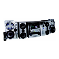
| Type | Mini Hi-Fi System |
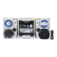
| Number of Discs | 3 |
| AUX Input | Yes |
| Tuner | FM |
General technical specifications including voltage, power, dimensions, and clock accuracy.
Audio amplifier output power, frequency response, and sound features.
FM, MW, and LW tuning ranges, sensitivity, selectivity, and distortion.
Warnings about ESD sensitivity of components and handling precautions.
General safety regulations and warnings about invisible laser radiation.
Instructions for connecting power, antennas, and speakers for optimal performance.
Detailed descriptions of controls on the system and remote for various functions.
Explanations of remote control buttons for CD, TUNER, CLOCK, MUTE, REPEAT, etc.
Common problems and solutions for CD, radio, tape, system, and remote control issues.
Details on accessing and using TUNER, QUARTZ, SERVICE PLAY, and DISPLAY test modes.
List of error codes, LED indicators, and test frequency tables for diagnostics.
Overall block diagram illustrating the main signal paths and component interactions.
Wiring diagram showing connections between major boards and components.
Block diagram and table of contents for the ECO6 tuner board.
Block diagram of the ECO6 tuner board.
Block diagram of the ETF7 tape module electronics (Dolby version).
Block diagram of the CD mechanism, photodiode, HF amplifier, and loader control PCB.
Block diagrams for the Mains board and P2001 power board.
Legend for symbols and table for tuner adjustment procedures.
Explanation of playback, recording, dubbing, and mode selector functions.
Details on amplifier, muting, bias, motor speed, and Dolby circuits.
Circuit diagram illustrating the servo control system for tape deck operation.
Procedures for adjusting motor speed, wow/flutter, azimuth, frequency response, and bias.
Procedures for adjusting Dolby playback level and frequency response.
Analog circuit diagram for the AF9 board.
Circuit diagram for the Dolby noise reduction and related circuits.
Warnings about capacitor discharge and steps for replacing the CD mechanism.
Warnings about charged capacitors, ESD, and necessary technician actions.
Main board circuit diagram part 2.
Explanation of the power amplifier IC, Super Class G operation, and its benefits.
Circuit diagram for the P2001 30-70W mains power supply.