EasyManua.ls Logo

Philips MCM9 Service Manual

Philips MCM9
77 pages
To Next Page IconTo Next Page
Page #1 background imageLoading...
Page #1 background image
MCM9/22/25/33
©
Copyright 2005 Philips Consumer Electronics B.V. Eindhoven, The Netherlands
All rights reserved. No part of this publication may be reproduced, stored in a retrieval system or
transmitted, in any form or by any means, electronic, mechanical, photocopying, or otherwise without
the prior permission of Philips.
Published by SL0521 Service Audio Printed in The Netherlands Subject to modifi cation.
GB
3141 785 30211
Micro System
TABLE OF CONTENTS
Page
Location of PC Boards & Versions Variation ........................1-2
Specifi cations .......................................................................1-3
Measurement Setup .............................................................1-4
Service Aids, Safety Instruction, etc ...........................1-5 to 1-7
Preparations & Controls .............................................1-8 to 1-9
Troubleshooting .................................................................. 1-10
Disassembly Instructions & Service positions ......................... 2
Service Test Program ...........................................................3-1
Set Block Diagram ................................................................ 4-1
Set Wiring Diagram .............................................................. 5-1
Front Board ............................................................................. 6
ECO Tuner Part : Systems Non-Cenelec .............................7A
Systems Cenelec .....................................7B
Mains board ............................................................................. 8
ETF8 Tape Module ................................................................. 9
CD-MP3-WMA 5250 Module ................................................. 10
Combi and Regulation board ................................................. 11
Mechanical Exploded View & Parts List ................................ 12
Revision list ........................................................................... 13
Version 1.1

Table of Contents

Other manuals for Philips MCM9

Question and Answer IconNeed help?

Do you have a question about the Philips MCM9 and is the answer not in the manual?

Philips MCM9 Specifications

Sound IconSound
output power2x100 watts music power
Loudspeakers IconLoudspeakers
woofer size5.25 inches
tweeter size2 inches
Connectivity IconConnectivity
headphone jack size3.5 mm
Convenience IconConvenience
eco power standby0.5 watt
Dimensions and Weight IconDimensions and Weight
set dimensions175 x 252 x 350 mm
main speaker dimensions175 x 252 x 215 mm
packaging dimensions524 x 353 x 408 mm
weight including packaging12.9 kg

Summary

Location of PC Boards

Version Variations

Details differences in features and boards across different model versions (MCM9/22, /25, /33).

System Specifications

Technical Parameters

Covers general, tuner, amplifier, cassette recorder, and compact disc performance specifications.

Measurement Setup Procedures

Tuner and CD Measurement Setup

Details test configurations and equipment for measuring tuner and CD playback performance.

Service Aids and Component Handling

Service Tools and Chip Handling

Lists necessary service tools, test discs, and safe procedures for handling chip components.

Repair Procedures and Information

Lead-Free Soldering and Service Instructions

Covers identification and procedures for lead-free soldering and critical post-repair checks.

System Connections and Operation

Antenna, Speaker, and Power Connections

Guides on connecting external antennas, speakers, and the AC power cord.

Remote Control Usage and Battery Installation

Explains remote control operation, sensor use, and battery replacement.

Functional Overview

Main Unit and Remote Control Functions

Describes the operation of buttons and features on the main unit and remote control.

Troubleshooting Guide

Common Problems and Solutions

Lists common issues like poor reception, no disc, and unresponsiveness, with their solutions.

Dismantling Instructions

Cover Cassette, Loader, and Front Panel Removal

Details the steps to remove the cover cassette, universal loader, and front panel assembly.

Further Dismantling Procedures

Front and Rear Panel Dismantling

Instructions for dismantling the front panel assembly and the rear panel assembly.

Service Positions and Repair Hints

Board Handling and Service Access

Advises on board disconnection, flex cable handling, and specific service positions.

Service Test Program

Test Modes and Procedures

Details test modes for Tuner, Tape, CD, Display, and ADC functions.

Set Block Diagram

System Signal Path Overview

Illustrates the main signal flow through the system's functional blocks.

Set Wiring Diagram

Component Interconnection Details

Shows the wiring connections between various components and boards.

Front Board Section

Front Board Contents Overview

Lists the sections covered within the Front Board chapter.

FTD Display Pin Connections

Display Pinout Details

Shows pin connections for different display modes and functions.

Display Board Component Layout

Display Board Component Placement

Provides a visual layout of components on the display board.

Display Board Chip Layout

Display Board Chip Placement

Shows the physical placement of chips on the display board.

Display Board Circuit Diagram Part 1

Display Board Schematic Details

Part 1 of the electrical schematic for the display board.

Display Board Circuit Diagram Part 2

Display Board Schematic Details

Part 2 of the electrical schematic for the display board.

Display Board Variants and Top Key Board

Display Board Variant Table

Lists variations in components for the display board across different models.

Top Key Board Overview

Covers component layout, chip placement, and circuit diagram for the top key board.

Control Board Layouts

Component and Chip Layouts

Visual representation of component and chip placement on the control board.

Control Board Circuit Diagram Part 1

Control Board Schematic Details

Part 1 of the electrical schematic for the control board.

Control Board Circuit Diagram Part 2

Control Board Schematic Details

Part 2 of the electrical schematic for the control board.

EEPROM Board Details

EEPROM Board Layouts and Diagram

Covers component layout, chip layout, and circuit diagram for the EEPROM board.

Electrical Parts - Front Board

Front Board Component List

Lists electrical parts required for the front board assembly.

ECO6 Tuner Board Overview

ECO6 Tuner Board Block Diagram

Illustrates the functional blocks and signal paths of the ECO6 tuner board.

Tuner Board Schematic

Tuner Board Schematic Diagram

Detailed electrical schematic of the tuner board.

Tuner Adjustment Table

FM/MW/LW Tuning and Alignment Settings

Provides parameters for tuning and alignment of FM, MW, and LW bands.

Tuner Board Layouts

Tuner Board Component and Copper Views

Visual layout of components on the component and copper sides of the tuner board.

Electrical Parts List - ECO6 Systems

Non-Cenelec System Parts

Lists electrical components for the ECO6 Non-Cenelec version.

Mains Board Introduction and Socket

Regulator Board Introduction

Explains the function and power supply provisions of the regulator board.

Mains Socket Connections and Layout

Details the wiring and layout of the mains socket.

Mains Board Component Layout

Component Placement Diagram

Visual layout showing component placement on the mains board.

Mains Board Chip Layout

Chip Placement Diagram

Visual layout showing chip placement on the mains board.

Mains Board Circuit Diagram

Electrical Schematic Details

Detailed electrical schematic of the mains board.

Electrical Parts - Mains Board

Mains Board Component List

Lists electrical parts required for the mains board.

ETF8 Tape Module

Connector Assignments

Details pinouts for various connectors on the ETF8 tape module.

Tape Deck Mechanics Overview

Tape Deck Wiring and Electronics

Covers wiring diagrams and mechanism electronics for tape decks.

Tape Deck Diagnostics and Control

Tape Adjustment and Block Diagram

Includes tape adjustment table and HEF4094BT functional block diagram.

Tape Module Layouts

Component and Chip Layouts

Visual layout of components and chips on the tape module.

Tape Module Circuit Diagram

Tape Module Electrical Schematic

Detailed electrical schematic of the tape module circuitry.

Autoreverse Tape Mechanism

Mechanical Parts List

Lists mechanical parts for the autoreverse tape mechanism.

Non-Autoreverse Tape Mechanism

Mechanical Parts List

Lists mechanical parts for the non-autoreverse tape mechanism.

Tape Module Exploded View and Parts

Exploded View and ETF8 Parts List

Visual assembly diagram and electrical parts list for the ETF8 board.

CD Drive Service Hints and Procedures

Playability, Lens Cleaning, and Laser Measurement

Troubleshooting steps for skipping tracks, lens care, and laser current measurement.

General CD Drive Hints

Operational tips, sensitivity checks, and general handling guidelines.

CD Drive Dismantling and Assembling

Drawer Dismantling, Assembling, and Emergency Opening

Guides for opening, removing, reassembling the CD drive drawer, and emergency access.

CD Audio Decoder Pin Description

SAA7824 Pinout Details

Lists pins and their functions for the SAA7824 CD audio decoder IC.

CD Audio Decoder Block Diagram

SAA7824 Internal Structure

Shows the internal functional blocks of the CD audio decoder IC.

Universal Loader Block Diagram

Loader IC Architecture

Illustrates the system architecture and IC connections of the universal loader.

Tray Motor Board Information

Tray Motor Board Layout and Switch Function

Covers the board layout, component placement, and tray switch operation.

CD Section Circuit Diagram

CD Section Schematic Details

Electrical schematic detailing the CD drive section's circuitry.

Audio Section Circuit Diagram

Audio Section Schematic Details

Electrical schematic for the audio output stage.

Flash Memory Section Circuit Diagram

Flash Memory Schematic Details

Electrical schematic for the flash memory component.

Disc Interface Circuit Diagrams

1-Disc and 5-Disc Interface Schematics

Circuit diagrams for 1-disc and 5-disc loading configurations.

Main Board Interface Circuit Diagram

Microcontroller Interface Schematic

Details the interface connections between the microcontroller and other components.

Power Supply and Control Circuit Diagram

Power Supply and Control Schematics

Shows circuit diagrams for power supply regulation and control functions.

CD Board Layout Diagrams

CD Board Top View Layout

Component placement diagram for the top side of the CD board.

CD Board Layout Diagrams

CD Board Bottom View Layout

Component placement diagram for the bottom side of the CD board.

Universal Loader Mechanical Exploded View

Mechanical Parts List

Lists mechanical parts for the universal loader assembly.

Universal Loader Electrical Parts List

Loader Board Component Lists

Lists electrical parts for the motor board and WMA-MP3-CD board.

Combi and Regulator Boards Overview

Regulator Board Information

Covers regulator board introduction, views, and circuit diagram.

Combi Board Information

Covers combi board views, diagrams, and parts list.

Regulator Board Layouts

Component and Copper Side Views

Visual layout of components on the component and copper sides of the regulator board.

Regulator Board Circuit Diagram

Electrical Schematic Details

Detailed electrical schematic of the regulator board.

Combi Board Component Layout

Hole Mounted Components Layout

Visual layout of hole-mounted components on the combi board.

Combi Board Copper Side View

Component Placement Diagram

Visual layout showing component placement on the copper side of the combi board.

Electrical Parts Lists

Regulator and Combi Board Parts

Lists electrical components for the regulator and combi boards.

Combi Board Circuit Diagrams

Source Selector and Amplifier Schematics

Schematics for the source selector and amplifier sections of the combi board.

Set Mechanical Exploded View

Main Unit Mechanical Assembly

Visual breakdown of the main unit's mechanical parts and their assembly.

Mechanical & Accessories Lists

Main Unit Screw Lists and Accessories

Lists screws, accessories, and mechanical parts for the main unit.

Revision List

Document Version History

Details changes and updates made across different versions of the manual.
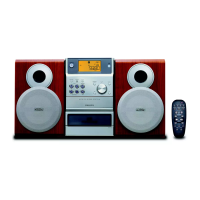
Related product manuals