47
1. 4.5.2.
Counter and input control
Counter input control
The
counter
accepts the data pulses from the ADC output and, in the
frequency mode
(Hz) from
the
comparator output.
The CT/ADC input (P10)
from the pP enables either the
ADC
input (CT/ADC
=
0)
or
the comparator input
(CT/ADC
=
1).
Data from the ADC
is routed to exclusive-OR gate D1910 pin 1 where the
varying duty-cycle is compared
with
a
'0'
(applied from
the
AZ output
of
flip-flop D1903) for
the first measuring period and with a
'1'
for
the
second
measuring period. This inverts the
data
for the second
measuring period. The output on pin
3 is
applied to
NAND-gate input D1914-9.
The clock ADC pulses
are applied to the other input
(8),
which produce
a
number of output pulses during the first period corresponding with
the
pos.
time of the duty cycles.
The output on D1914-10
is applied
to
another exclusive-OR
gate. D1909-9,
one input
of
which is tied to
logic
'V.
The resultant output
for
the complete measurement is equal to the
mean value of the two measuring
periods. The
output on D1910-10
is
presented
to two
NAND-gates, which in the ADC
selected
mode act as
inverters only
because of
a permanent logic
'1'
on the other inputs (D1914-5 and D1 91
3-2,3).
The output
feeds the counters D1902
and D1907 in
cascade.
In the frequency
mode, the
CT/ADC input is at logic ‘V.
The
NAND-gate
D1914
(12, 13,
11)
wired
as an
inverter gives an output
'0'
to
NAND-gate
D 191
4-5
feeding
the
ADC input
of
the
counter. This
applies
a
permanent
'1'
to
final NAND-gate
D1913
input 1.
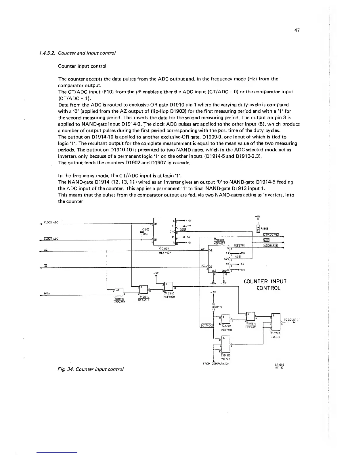
This means that the
pulses from
the comparator output are fed, via two
NAND-gates acting
as
inverters,
into
the counter.
-5V
FROM
COMPARATOR
ST3386
811130
F/g.
34. Counter input
control