Mechanical Instructions
EN 19Q552.1A LA 4.
2010-Jun-25
back to
div. table
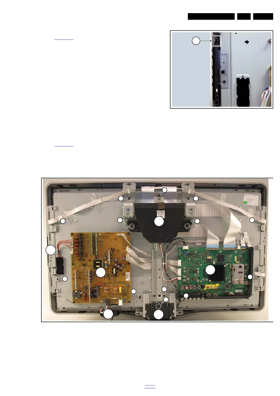
4.5.7 Local Control Board
Refer to Figure 4-17
for details.
1. Unplug the connector on the IR & LED board that leads to
the Local Control board as described earlier.
2. Release the cable from its clamps/tape.
3. Release the clip on top of the unit [1] and take the unit out.
When defective, replace the whole unit.
Figure 4-17 Local Control board
4.5.8 LCD Panel
Refer to Figure 4-18
for details.
1. Remove the Stand and IR/LED board [A] as earlier
described.
2. Remove the Speakers/Subwoofer [B] as earlier described.
3. Remove the PSU [C] and SSB [D] as earlier described.
4. Remove the Mains Switch [E] as earlier described.
5. Remove the Local Control board [F] as earlier described.
6. Remove the brackets [1].
7. Remove the clamps [2].
8. Remove the flare.
Now the LCD Panel can be lifted from the front cabinet.
Figure 4-18 LCD Panel removal (based on 32" AL model)
4.6 Set Re-assembly
To re-assemble the whole set, execute all processes in reverse
order.
Notes:
• While re-assembling, make sure that all cables are placed
and connected in their original position.
• Pay special attention not to damage the EMC foams in the
set. Ensure that EMC foams are mounted correctly.
18770_145_100216.eps
100217
1
18970_112_100326.eps
100326
1
1
1
1
2
2
1
2
2
1
1
1
C
D
A
B
E
1
F