Technical Specifications, Diversity, and Connections
EN 3Q552.1A LA 2.
2010-Jun-25
back to
div. table
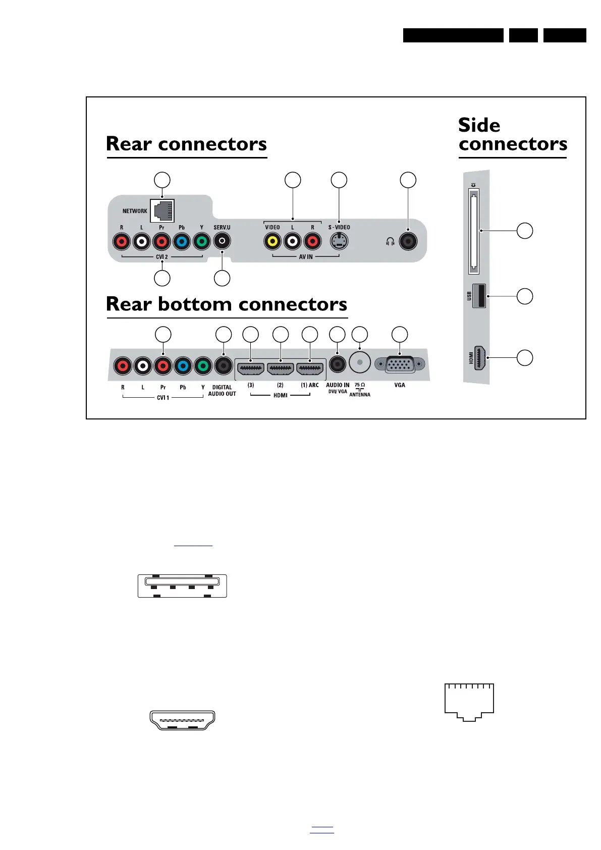
2.3 Connections
Figure 2-1 Connection overview
Note: The following connector colour abbreviations are used
(acc. to DIN/IEC 757): Bk= Black, Bu= Blue, Gn= Green, Gy=
Grey, Rd= Red, Wh= White, Ye= Yellow.
2.3.1 Side Connections
1 - Common Interface
68p - See diagram B01F HDMI & CI
jk
2 - USB2.0
Figure 2-2 USB (type A)
1-+5V k
2 - Data (-) jk
3 - Data (+) jk
4 - Ground Gnd H
3 - HDMI: Digital Video, Digital Audio - In
Figure 2-3 HDMI (type A) connector
1 - D2+ Data channel j
2 - Shield Gnd H
3 - D2- Data channel j
4 - D1+ Data channel j
5 - Shield Gnd H
6 - D1- Data channel j
7 - D0+ Data channel j
8 - Shield Gnd H
9 - D0- Data channel j
10 - CLK+ Data channel j
11 - Shield Gnd H
12 - CLK- Data channel j
13 - Easylink/CEC Control channel jk
14 - n.c.
15 - DDC_SCL DDC clock j
16 - DDC_SDA DDC data jk
17 - Ground Gnd H
18 - +5V j
19 - HPD Hot Plug Detect j
20 - Ground Gnd H
2.3.2 Rear Connections
4 - RJ45: Ethernet (optional)
Figure 2-4 Ethernet connector
1 - TD+ Transmit signal k
2 - TD- Transmit signal k
3 - RD+ Receive signal j
4 - CT Centre Tap: DC level fixation
18990_001_100401.eps
100401
10 11 1212 13 14 15 16
4 7 8 9
5 6
1
2
3
1 2 3 4
10000_022_090121.eps
090121
10000_017_090121.eps
090428
19
1
18 2
1123 45678
10000_025_090121.eps
090121