www.phocos.com 20 | P a g e
8. Switch on the AC input breaker of each unit in quick s uccession, if an AC source is installed.If this takes too
long, then some units may show fault 82 on their screen, b ut they will restart automatically and upon
detecting a valid AC input, will function normally.
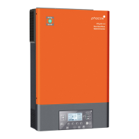
9. If a valid AC input source is de tected and thethree phases match with the unit settings in settings menu
number 28, they will work normally. Otherwise,the symbol will flash and Grid Mode will not function.
In this case, check that the order or the three phases is correct. If necessary, turn off all units and then switch
the setting in settings menu number 28 for all Phase L2 units to Phase L3 and vice-versa by following steps1
to 5. Then continue with step 7 . The displayswill now show thefollowing:
Screen of Units on Phas e L1 Screen of Units on Phase L2 Screen of Units on Phas e L3
10. If there are no further faults displayed, the 3-phase system ins tallation is complete.The breakers on the AC
output of each unit can be switched on and then loads may be connected.
Split-Phase (2-Phase), One or more Units per Phase
Follow these steps once the wiring is completed:
1. If PVis available, switch it on with its breaker. If an AC source is available, switch it on with its AC input
breaker. The turn on the battery breaker /insert the fuse. Finally, turn on one unit with its AC output on/off
switch.
2. In the Settings Menu (see chapter“Device Operation Settings”) navigate to setting s menu 28.
3. Turn the AC output on/off switch off to deactivate the AC output.The unit will remain in Stand-By mode for
under a minute and the display will stay on for this time.
4. Set the menu number 28 setting from the default value “Single”(SIG) to“Phase L1 for split-phase”(2P1). This
will not b e possible if the unit is not turne d off as described in the previous step. Press so the entry
stops blinking. Now press the button to ac cept thenew setting and return to the main view.
5. Switch off the PV and AC input breaker if the y were on. Once the s etting is confirmed, wait for the unit to
shut down automatically, the display will then turn off completely.
6. Repeat steps 1 to 5 with each further unit connected onthe same phase 1. Then repeat steps 1 to 5 for each
unit in phas e 2 and, instead of choosing “Phase L1 for split-phase”in step 4, choose“Phase L2 for split-phase”
(2P2).
7. Now turn on each unit. The units will show the following in their respectives creens:
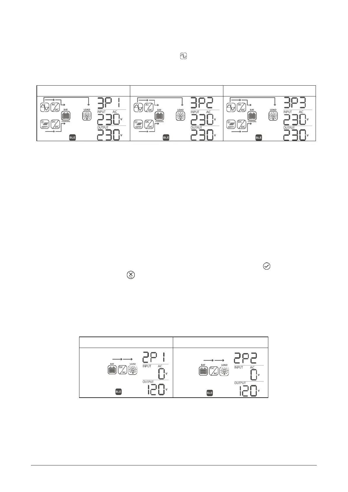
Screen of Units on Phas e L1 Screen of Units on Phase L2
8. Switch on the AC input breaker of each unit in quick succession if an AC source is installed. If this takes too
long, then some units may show fault 82 on their screen, b ut they will restart automatically and upon
detecting a valid AC input, will function normally. The displayswill showthe following:

 Loading...