16
MKT-0262 MPC-1748 Rev 02/13
Fitting an APM2 in an APM100 Enclosure
Instructions
2.2.4 Wiring
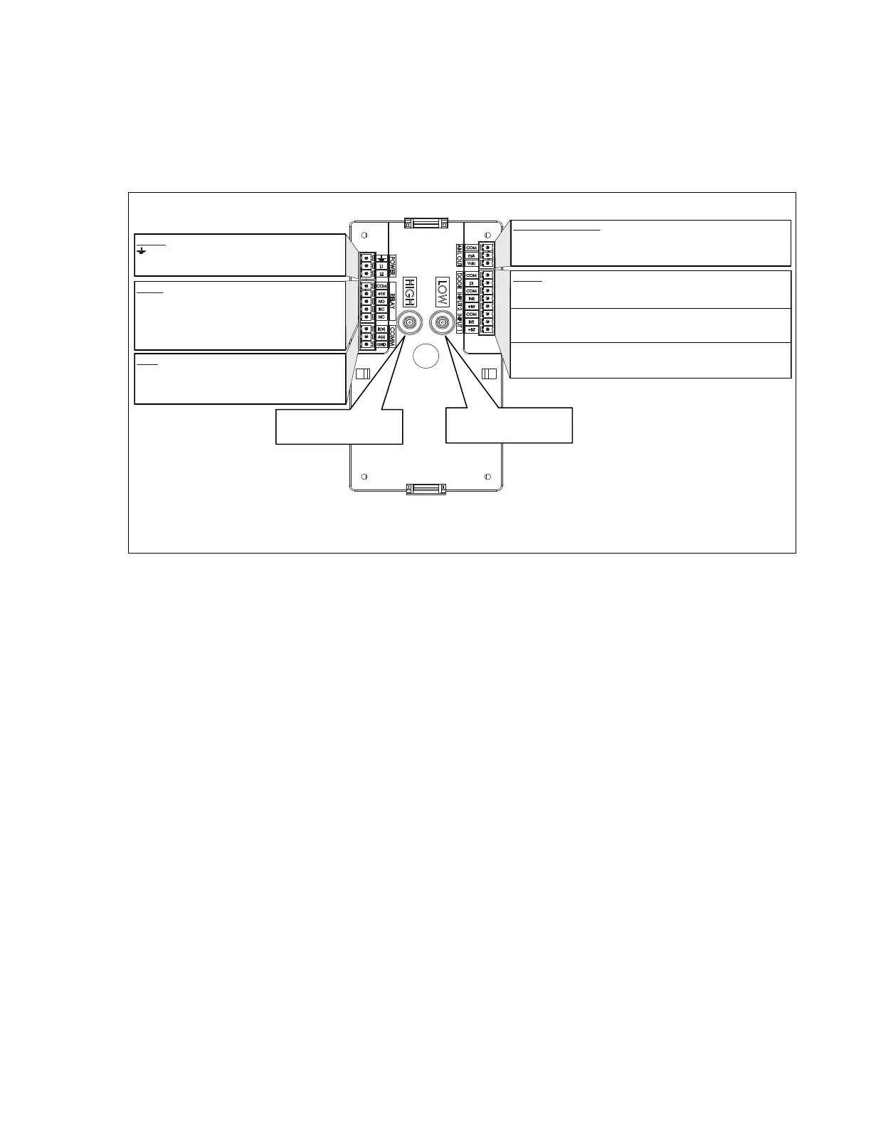
Figure 2-4. Rear View of the APM2 Showing Wiring and Plumbing Connections
The back of the APM2 has electrical connectors labeled with their function. The mating electrical connectors
(supplied) are color coded and labeled with the matching function.
Refer to the Advanced Pressure Monitor II User’s Guide (MKT-0263) for detailed wiring instructions.
2.2.5 Remotely Switching Alarm Setpoints
The APM100 model uses dry contacts to switch pressure setpoints between positive and negative, whereas the
APM2 uses an input voltage: 0, 5 or 10 Volts to switch pressure setpoints between negative-neutral-positive
respectively. If this function was used on the APM100 product, adaptations will need to be made to restore their
function with other equipment or devices that will generate the 0, 5 or 10 Volt signal.
ANALOG (ANL) OUTPUT
COM COM
mA Current Output (4-20 mA)
Vdc Voltage Output (0-5 Vdc, 0-10 Vdc)
INPUTS (wired to door N.O. contact)
COM COM Door
DI Digital Input
COM COM Analog Input2
IN2 Analog Input2 (0-5, 0-10Vdc)
+15 15 Vdc
COM COM Analog Input1
IN1 Analog Input1 (0-5, 0-10Vdc)
+15 15 Vdc
Earth Ground
L1 24 Vac
L2 24 Vac
HIGH or room pressure tubing
contacts here
LOW or reference pressure tubing
connects here
POWER
RELAY
COM COM
+15 +15 Vdc
NO Normally Open
RC Relay COM
NC Normally Closed
COM BACnet APM2-xx-ENG-BAC Products
B (+)
A (-)
GND
REAR VIEW
 Loading...