Advanced Pressure Monitor II Rough-In Installation
Installation Overview
3
MKT-0262 MPC-1748 Rev 02/13
APM2 Rough-In Installation Guide
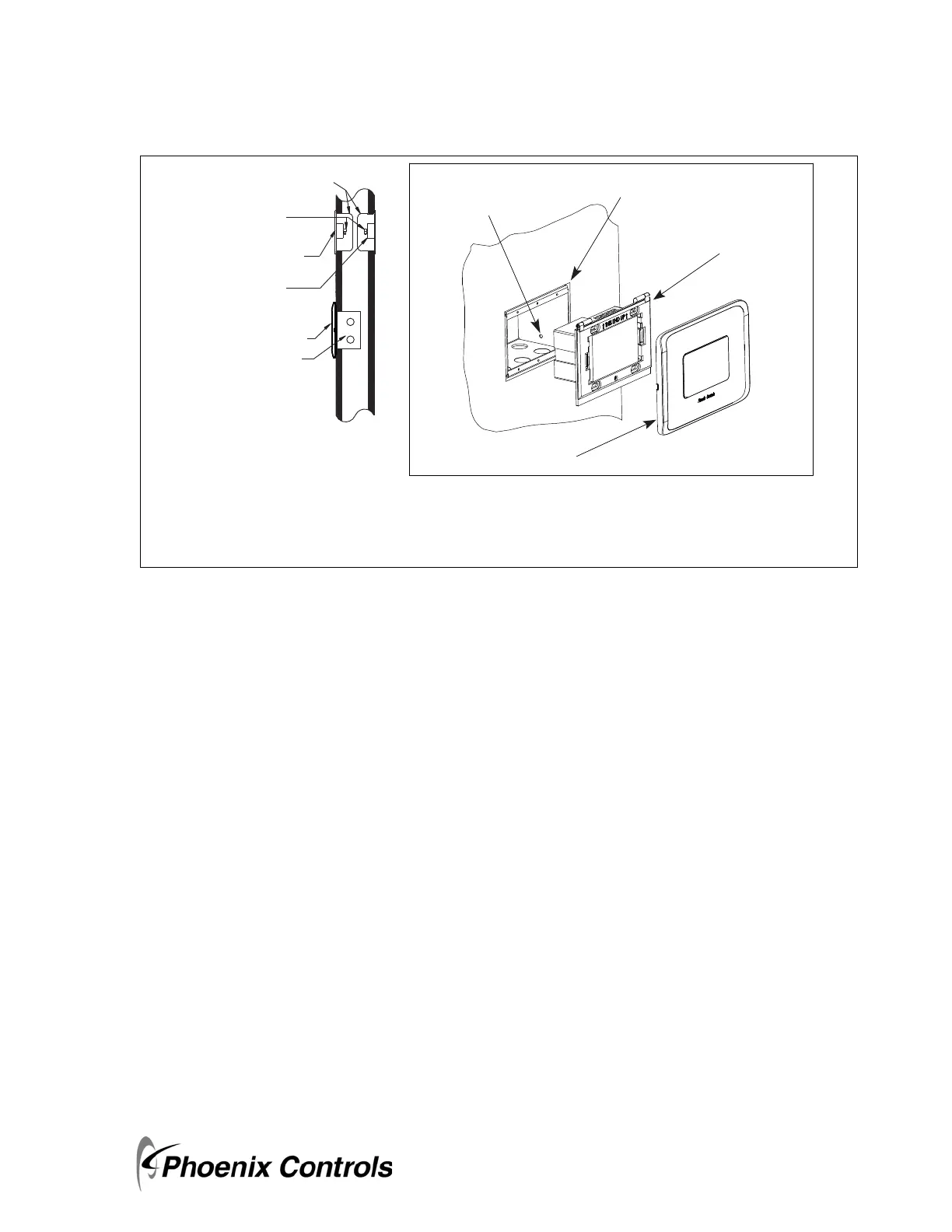
Figure 1-1. Wall Mount Installation Overview
1.3.1 Wiring Recommendations
• All circuits must conform to the requirements of an NEC Class 2 (dry) circuit.
• Use multiple transformers instead of larger transformers when more than 100 VA is required.
• Each pressurization zone should have either a dedicated single-phase primary circuit, or a secondary circuit
disconnect.
•Refer to Phoenix Recommended Cables on page 33 for approved cable manufacturers and wire types.
• Use stranded wire for ease of installation.
• Follow good wiring practices:
• Locate cables away from sources of electrical interference (EMI/RFI).
• Do not run signal or communication cable in the same conduit or wire way as power cables.
• If signal cable must cross power cables place these at a 90-degree angle.
• Shield or drain wires, if required, should be wrapped with insulating tape to prevent contact with exposed
conductors or contacts.
• Maintain a consistent color code or polarity all the way through the wiring system.
• Power supply and signal isolation on I/O devices vary from manufacturer to manufacturer. Verify the
wiring device manufacturer’s recommendations for isolating power and signal common connections and
maintain polarity.
• Local and national electrical codes take precedence.
Single Gang
Electrical Box
1/4" x .170 Tube Barb
(Conduit between
sensors and monitor
panel may be required.)
Reference
Pressure Pickup
Room
Pressure Pickup
APM2
NOTE: Connecting tubing and electrical
boxes are field-supplied.
Triple Gang Double Deep
Electrical Box
APM2 Faceplate
APM2
Rough-in Electrical Box
- Raco 697
- Appleton M3-350
Electrical Box
Mounting Hole
WALL MOUNT DIMENSIONS
Triple gang double deep electrical box—5.625" (220 mm) W x 3.5" (114.3 mm) H x 3.5" (63.5 mm) D
Single gang electrical box—2" (51 mm) W x 3" (76 mm) H x 3.5" (63.5 mm) D*
* Dimensions are approximate.
 Loading...