PicoQuantGmbH MultiHarpSoftwareV.3.1.0.0
5. Specific Measurement Tasks
5.1. Setting Up the Input Channels
Thissectionprovideshelpandinstructionsforthefirstbasicstepsofsettinguptheinstrument.However,ifyou
arerunningTCSPCmeasurementsforthefirsttimewestronglyrecommendyoureadtheprimeronTCSPCin
section2first.Alsoconsidertheliteraturelistedthere.
Inordertoacquireanydata,theinputchannelsandthesyncinputoftheMultiHarpmustbesettomatchtheir
electricalinputsignals.TheMultiHarpinputchannelsaredesignedidentically.Allinputshaveaprogrammable
leveltrigger(comparator)allowingtheselectionofthetriggeredge(rising=1,falling=0)andthetriggerlevelin
mV.Forspecificationdetailsseesection8.3.1andtakenoteofthemaximumratings.
Incaseofcoincidencecorrelationexperimentsusingtwoormoredetectors,theinputchannelsaretypically
usedforonedetectoreachanddataiscollectedinT2mode.Inthatcasethesyncinputcan(butneednot)be
usedforadetectoraswell.Ifaquickvisualizationofcoincidencecountsisrequired,itisalsopossibletouse
histogrammingmode.Inthatcase,onedetectorisconnectedtothesyncinput.Coincidencehistogramswillbe
collectedforeachinputchannelwithrespecttothesyncinput.Intime–resolvedfluorescencemeasurements
withapulsedexcitationsource(typicallyalaser)thesyncinputreceivesasyncsignalfromthelaser.Herewe
focusonthelatter,morecommoncase.Performthefollowingstepstosetuptheinputdiscriminators.
Using the Panel Meters
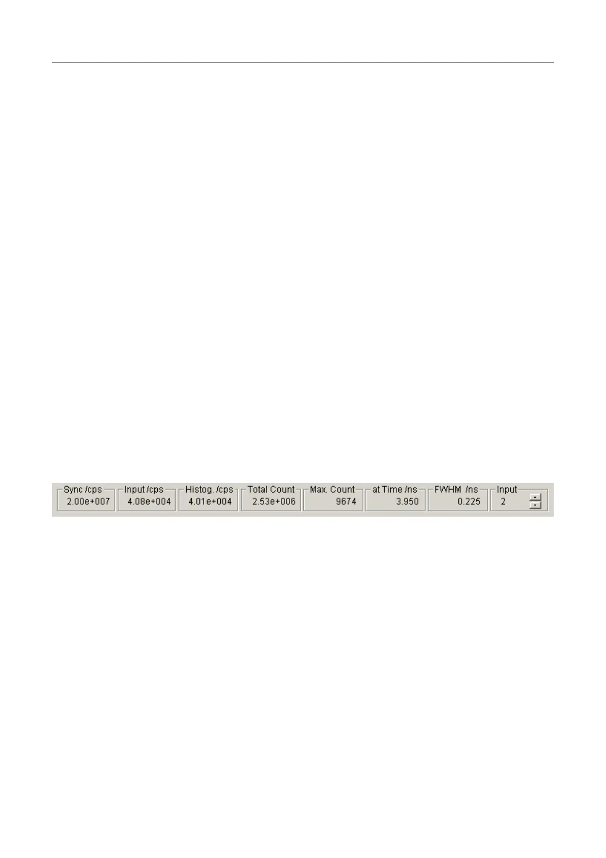
Atthebottomofthemainwindowyoufindasetofpanelmeters.Theseareveryimportantduringset–up.The
metersshowingunitsofcps(countspersecond)intheirtitleareratemeters.Theleftmostratemetershowsthe
syncinputrate.Thenextmetershowsthechannelinputrate.Notetheselectoratthefarrightofthepanelme-
ters.Thisselectsthechanneltheratemeters(exceptsync)arereferringto.Selectthechannelyouarecurrently
settingup.Notethattheratemetersuseafixedgatetimeof100ms.Theiraccuracyatlowratesistherefore
limited.Theyreallyonlyserveasaquickmeansofdiagnosticsandshouldnotbeusedtoobtaindefinitivemea-
surementresults.
Theothermetersshowthehistogrammingrate,thetotalcountinthehistogram,themaximum(peak)countand
thepositionofthemaximum.Allofthesevaluesdependontheinputselector.
NotethattheInputselectoralsohasaselectionoptionlabeledSum.Inthiscasethemetersarefedfromthe
sumofallinputchannels.Thisisthedefault.
Setting up the Sync Input
Fortypicalfluorescencedecaymeasurements,the MultiHarp needsanelectricalsyncsignalfromthelight
source.ThePDLSeriesofdiodelasersfromPicoQuantprovidesthissignaldirectly.Ifthelaserdoesnotpro-
videanappropriateelectricalsyncsignal(e.g.,someTi:Salasers),asyncdetector(photodiode)suchasthe
TDA200mustbeused.Thesyncsignalmustconsistofpulseswithsteepnessandamplitudematchingthe
specificationsoftheMultiHarpandthetriggeredgemustbesettotheleadingedge(rising=1,falling=0).Forex-
ample,aNIMtypesignalisappropriate.Thisisasteepnegativepulse(0.5to10nswide,activeedgefalling)of
typically−800mVinto50Ω.TheMultiHarpcanactuallyhandle±1.2Vbutlargeamplitudesmaycauseexcess
interferenceandcross-talk.betweentheinputs.Amplitudesaround100to200mV(onallinputs)arebestin
termsoftimingaccuracyandlowesthistogramrippleduetocross-talk.Itmaythereforebeadvantageoustoat-
tenuateNIMpulsesby10or15dB.Lowestcross-talk.istypicallyachievedbyusingsignalsofsimilarampli-
tudeonallinputs.SMAin-lineattenuatorsofsuitablebandwidthcanbeusedtoadjustthis.Thetriggerlevelis
adjustableforoptimumtimingaccuracy.Initiallyyoushouldsetittohalfofthesyncpulseamplitude.Lateritcan
befine-tunedempirically.
Unlessyouaresurewhatkindofsignalyoursyncsourcedelivers,useafastoscilloscope(50Ωinput)tocheck
thepulseshape,polarityandamplitude.Theleadingedgeshouldbesteep(ideally2nsrise⁄falltimeorfaster),
thereshouldalsobenoexcessiveringing.Thepulsewidthshouldbeatleast0.4ns,theupperlimitisnotcriti-
cal.
Page31