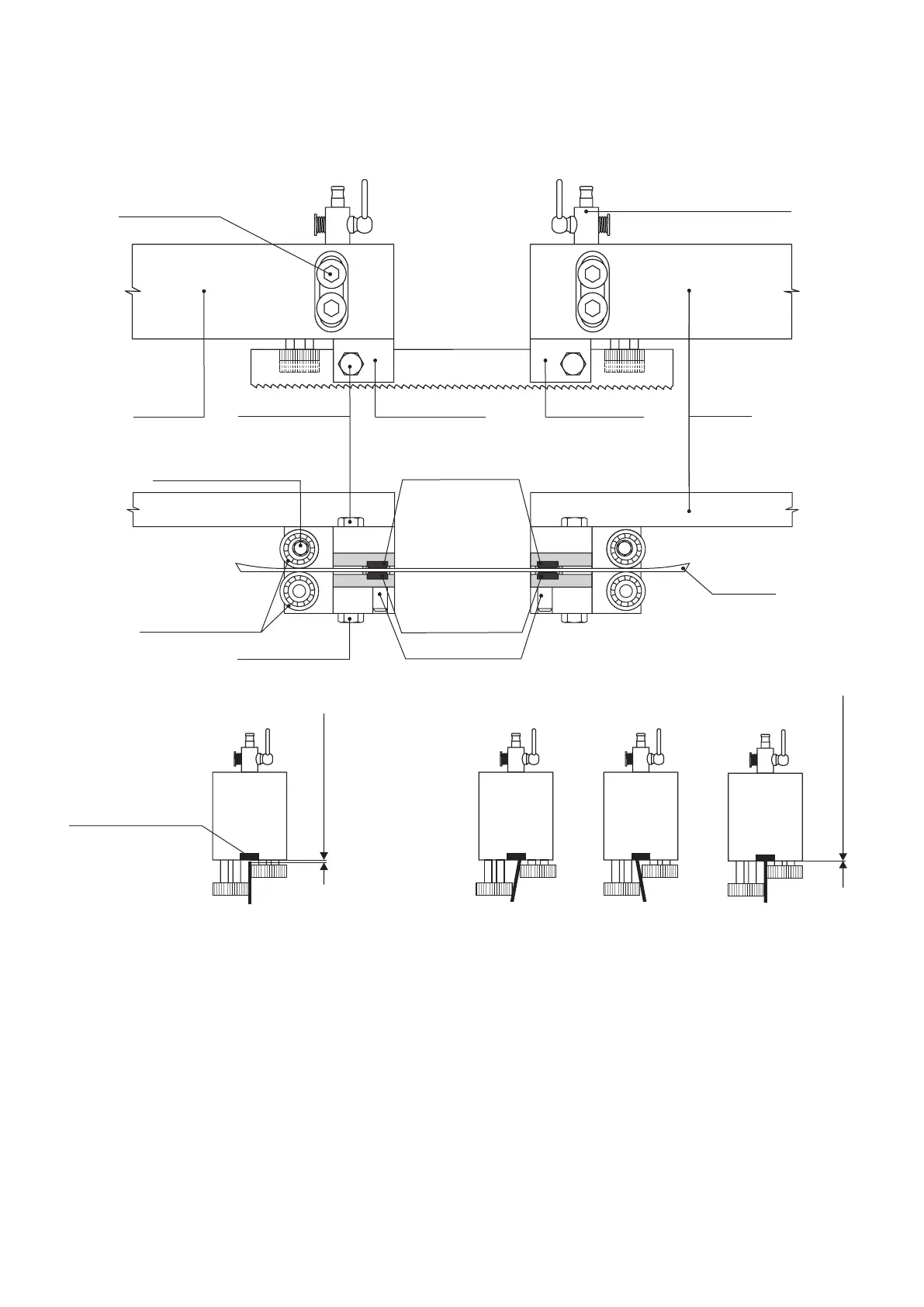
Guide Head Setting Procedure
Switch off the MAIN SWITCH or disconnect the machine from the mains and secure it against restarting. Close the oil damper relief
valve (see Section 4.2.) and raise the arm to about 20 mm above the fixed jaw of the vice. Set the movable guide head, so that the
distance between the guide heads is approximately 20 cm. Disconnect the inlet hoses from the coolant valve. Remove the protective
covers of the saw blade and open/remove the back cover of the arm (see section 4.6.), if necessary lift the arm about 20 mm above the
fix camping jaw again. Loosen the tensioning star, take the saw blade off the wheels and push it off the guide heads. Unscrew the guide
heads gradually from the fixed and movable bars, turn them by 180 ° (with bearings and hardened steel blade guides facing upwards)
and screw back to the bars. Make sure that the guide heads are perpendicular to the guide bars and that the height of the guide heads
is identical. If you find special washers between the guide head and the bar, make sure you place them back afterwards. Check the
tightening of the fixed hardened steel blade guides. Insert approximately 30 cm of an old saw blade in the guide heads between the
hardened steel blade guides and the bearings. Set the hardened steel blade guides using the width adjusting screw, so that the saw
blade does moves between the guides without any play and jamming. When the saw blade has been adjusted, set the eccentrically
mounted bearings in such a manner that the bearings do not “cut” the saw blade, but at the same time you have to prevent too much
space for the saw blade between the bearings. When the saw blade moves, the bearings are carried along by the saw blade. Make
sure that all bolt connections are tight. Unscrew the guide heads from the bars. Fit the saw blade on the wheels, check its correct
alignment on the wheels and tension the saw blade. Install both guide heads on the saw blade in the space between the bars and
adjust them in the correct position on the bars. Distinguish the correct height setting of the guide heads based on the machine type.
ECCENTRIC BEARING SCREW
HARDENED STEEL
BLADE GUIDES WIDTH
ADJUSTING SCREW
ECCENTRICALLY
ARRANGED BEARINGS
HARDENED STEEL
BLADE GUIDE SCREW
MOVABLE HARDENED
STEEL BLADE GUIDES
FIXED HARDENED
STEEL BLADE GUIDES
MOVABLE
GUIDE BAR
FIXED
GUIDE BAR
MOVING GUIDE HEAD
GUIDE HEAD SCREW
SAW BLADE
Incorrect saw blade guidance
Correct saw blade guidance
to center between guide bearings
UPPER HARDENED
STEEL BLADE GUIDES
Approximately 0,5-1 mm
WARNING!
There has to be a clearance
COOLANT VALVE
FIXED GUIDE HEAD
HARDENED STEEL
BLADE GUIDE SCREW
4.8. Guide Heads Adjustment
The correct setting of the bearings and the hardened steel blade guides in the guide heads substantially influences the saw
blade life and the quality of the cut. The eccentrically arranged guide head bearings must be set in such a manner that the saw
blade surface is parallel to the surface of hardened steel blade guides with a minimum play (clearance) between the plates and the
blade.