Pilz GmbH & Co. KG, Felix-Wankel-Straße 2, 73760 Ostfildern, Germany
Telephone: +49 711 3409-0, Telefax: +49 711 3409-133, E-Mail: pilz.gmbh@pilz.de
4-1
4.1 Device properties
4 Function description
44000Function descriptionFunction description4-4.1Device properties4100Device properties4-
4.1.1 Integrated protection mechanisms
Integrated protection mechanisms4-Sicherheitseigenschaften_multi_allgemein
The relay conforms to the following safety criteria:
The circuit is redundant with built-in self-monitoring.
The safety function remains effective in the case of a component fail-
ure.
Sicherheitseigenschaften_Halbleiter
The safety outputs are tested periodically using a disconnection test.
4.1.2 Operation
Operation4-Funktionen_multi_Basis_ohne_Erweiterung
The function of the safety system's inputs and outputs depends on the
safety circuit created using the PNOZmulti Configurator. A chip card is
used to download the safety circuit to the base unit. The base unit has
2 microcontrollers that monitor each other. They evaluate the input cir-
cuits and switch the outputs accordingly.
The LEDs indicate the status of the PNOZmulti safety system.
The LC display indicates the status of the inputs/outputs and the supply
voltage.
The online help on the PNOZmulti Configurator contains descriptions of
the operating modes and all the functions of the PNOZmulti safety sys-
tem, plus connection examples.
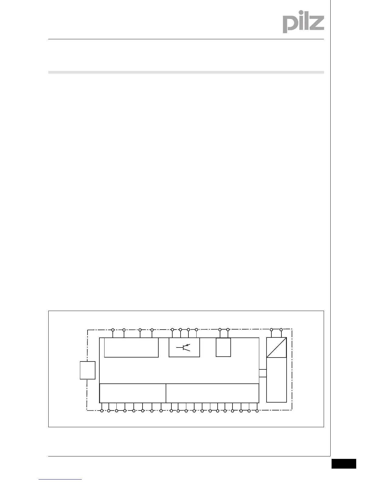
4.1.3 Block diagram
Block d iagram4-Blockschaltbild

 Loading...


