OPERATING MANUAL PSEN op4F/H-A series
In alignment mode, the light curtain is always in a safe state and the OSSD outputs are OFF.
The quality and level of the alignment is determined via the signal strength of each individual
beam in alignment mode. The two synchronization beams have a higher value level. The
user can see the alignment quality from the LED state at the lower end of the receiver.
A. Hold the receiver in a stable position and align the transmitter until the yellow SYNC1
LED goes out. This state confirms that the first synchronisation beam has been
aligned.
B. Rotate the transmitter around the axis of the lower lens until the yellow SYNC2 LED
goes out.
C. For precision adjustment, make minor movements of the transmitter and receiver to
achieve the optimum quality
D. Attach both units firmly using the mounting brackets. Check that the LEVEL of the
r
eceiver does not decrease in quality and that the light axes are not interrupted. T
hen
c
heck that all LEDs on the LEVEL display go out, even if only one beam is
interrupted. This test is conducted using a test object TP-14 or TP-30 corresponding
to the resolution (see Chapter 2.2.5).
E. Switch off the light curtain pair and then switch it back on in normal operating mode.
The alignment level is also monitored by the display during normal operation (see
Chapter 8.1). Once the light curtain has been aligned and fastened appropriately, the
LED display proves perfect for checking the alignment and displaying any change i
n
t
he ambient conditions (e.g. dust).
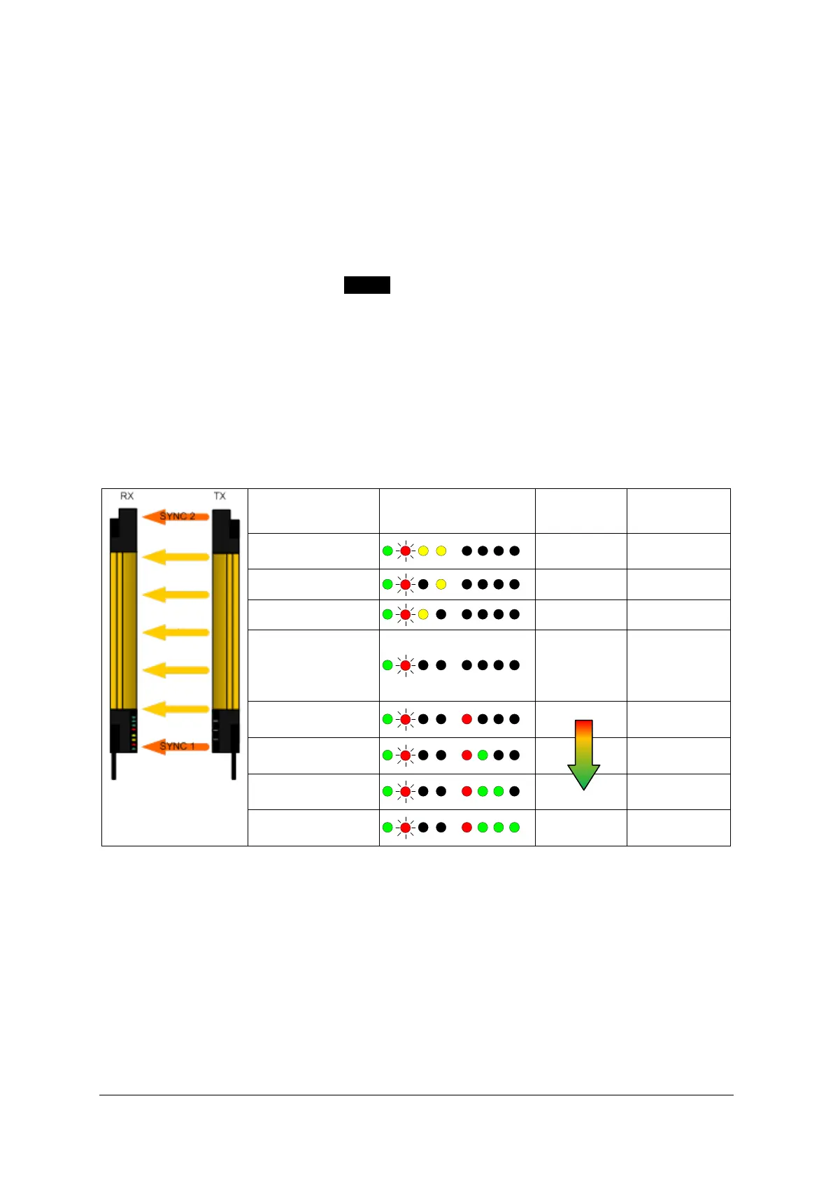
Display Configuration LED RX
Alignment
status
Status of OSSD
in normal
NONE OFF
SYNC1 aligned NONE OFF
SYNC2 aligned NONE OFF
intermediate
beams
NONE OFF
All light axes are
aligned
ON
All light axes are
aligned
ON
All light axes are
aligned
ON
All light axes are
aligned
EXCELLENT
ON
Fig. 29 –Status of the LED displays in alignment mode

 Loading...
