Installation and alignment
Operating Manual PSEN sc B 5 Series
1004508-EN-02
31
6.4 Installation with setting of angle of inclination/roll angle -
bracket PSEN sc bracket P
} The setting of the angle of inclination of the safety laser scanner is not changed when
exchanging the safety laser scanner.
Prerequisites
} Mounting surface with 2 drill holes, 10mmdeep, distance 73mm horizontally towards
each other for fixing the PSENscbracketPR or PSENscbracketP
} The protective bracket PSENscbracketH must already be fixed at the safety laser
scanner (see
Installation of the protective bracket PSEN sc bracket H at the safety laser
scanner [ 30]).
[5]
[7]
[6]
[8]
[1]
[2]
[3]
[4]
[4]
[3]
[7]
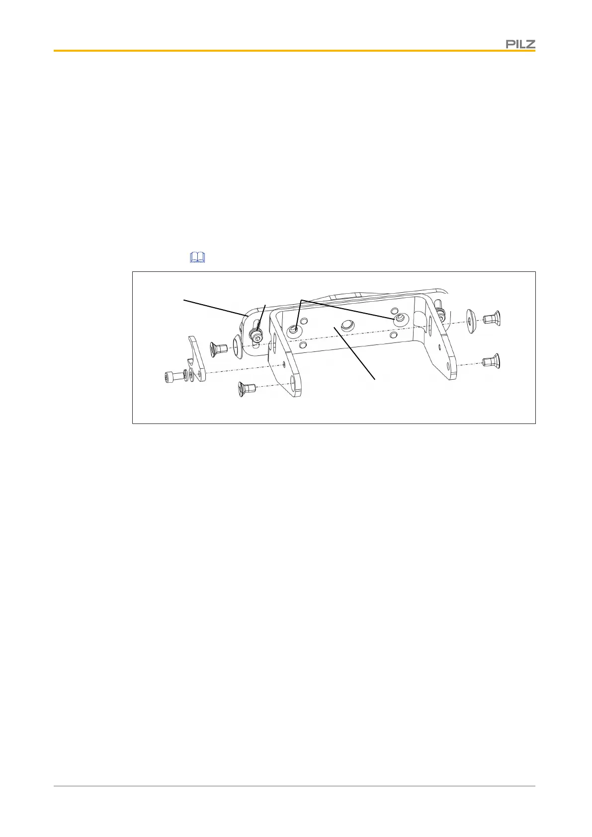
Legend
[1] Adjusting disc for angle of inclination
[2] Set screw for adjusting disc for angle of inclination
[3] Fixing screws for safety laser scanner
[4] Fine adjustment screws for the incline of the safety laser scanner
[5] Front part of the PSENscbracketPR
[6] Fixing screws for fixing to the mounting surface
[7] Roll angle fine adjustment screws
[8] Rear part of the PSENscbracketPR
Procedure:
1. Loosen the roll angle fine adjustment screws [7] of PSENscbracketPR slightly, if re-
quired, and align the front part [5] of PSENscbracketPR to the rear part [8].
The bracket is pre-assembled.
2. Fix PSENscbracketPR with the fixing screws [6] to the mounting surface and tighten
the fixing screws [6] alternately and evenly with 3 Nm.
3. Fix the adjusting disc for angle of inclination [1] with the set screw and washers [2] at
PSENscbracketP (right or left).
4. Align the middle of the adjusting disc for angle of inclination [1] with the center of the fix-
ing for the safety laser scanner [3] and tighten the set screw for the adjusting disc for
angle of inclination [2] with 2,5 Nm.
 Loading...