5-1PSS(1) ControlNet Adapter - Hardware Manual
Module
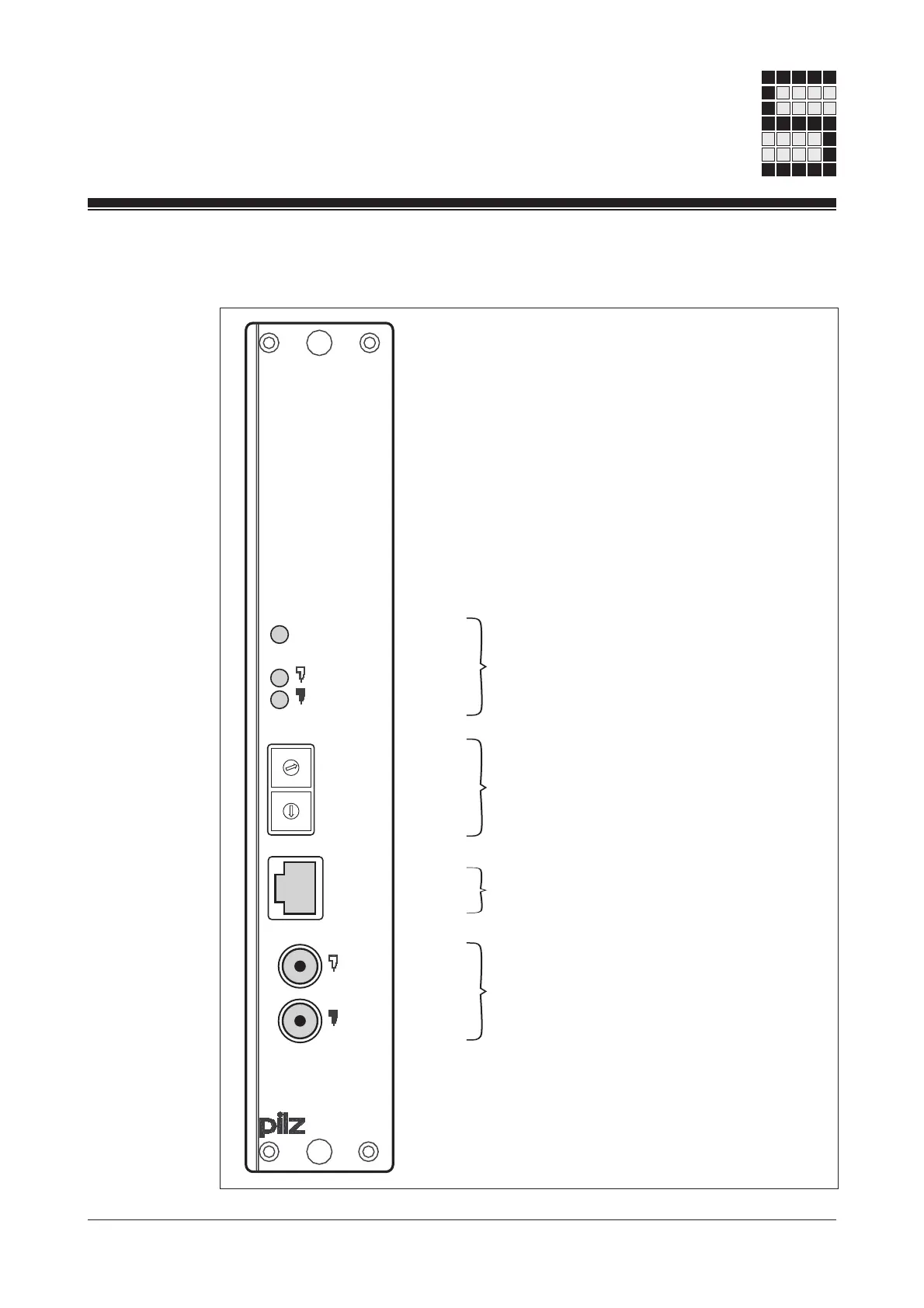
Front view
Fig. 5-1: Front view
NAP
B
module status
A
net
address
x 10
x 1
ControlNet
5
4
3
2
1
0
9
8
7
6
5
4
3
2
1
0
9
8
7
6
B
A
Operating status and error LEDs:
• Communication: module and PSS
(module status)
• Communication: ControlNet
(channel A and B)
Rotary switches to set the
Net Address
Network Access Port (NAP) for
temporary access
Interfaces to connect to ControlNet
(channel A and B)

 Loading...