1-2
Chapter 1: Card Installation & Hardware Setup
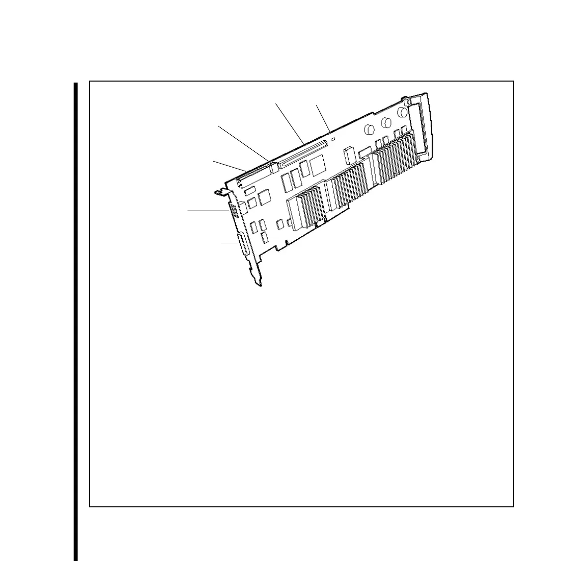
Digital Tether Connector (36-pin female) -- This connector is where the TARGA 3000 Pro Analog or Pro
Digital Breakout Box is connected. It accepts input from and provides output to the Pro Analog Breakout Box
in parallel ITU-R BT.656 format. The connector also inputs to and accepts the serial digital format from the
Pro Digital Breakout Box.
1394 Connector (6-pin male) -- This connector allows you to connect a digital camcorder or VTR via a
IEEE-1394/iLINK cable to the TARGA 3000 card. The connection will accept both video and audio signals,
but note that no power is output from this connection.
VIP Connector (26-pin male) -- This connector is for future expansion card capability or use.
1394 Connector (4-pin female) -- This connector allows you to connect a digital camcorder or VTR via a
IEEE-1394/iLINK cable to the TARGA 3000 card. The connection will accept both video and audio signals.
No power is output from this connection.
A/V I/O Connector (180-pin female) -- Allows an audio/video module (i.e., daughter card) to be connected to
the TARGA 3000 card for signal processing.
LED -- When the TARGA 3000 card is installed, this LED momentarily flashes every time the computer is
powered up. If this LED displays a steady light and does not go out once the computer is powered up, then the
TARGA 3000 card is damaged. Refer to “Appendix A: Troubleshooting & Contacting Pinnacle Systems.”
Figure 1-1 TARGA 3000 Card
1394 Connector
(6-Pin Male)
Digital Tether Connector
VIP Connector
1394 Connector
(4-Pin Female)
A/V I/O Connector
LED
 Loading...
