PDP-435PE
30
1234
1234
C
D
F
A
B
E
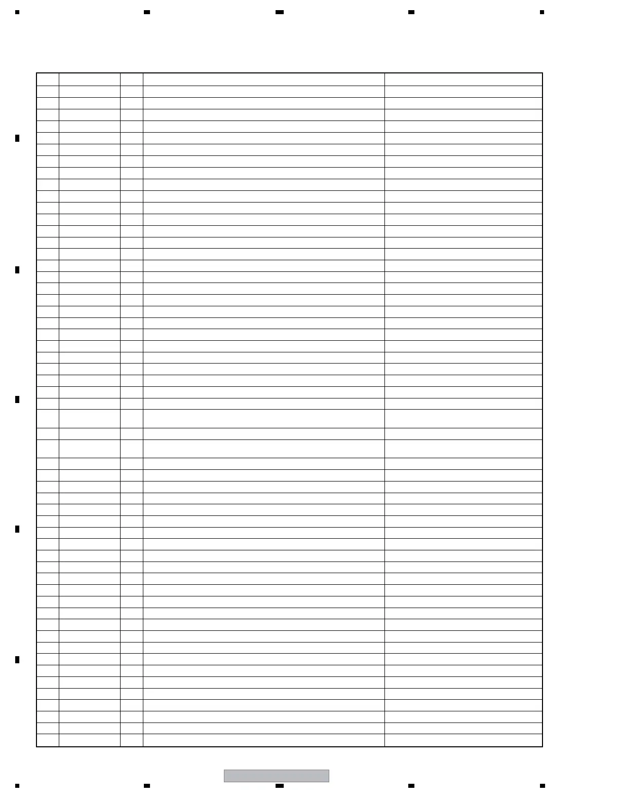
No. Signal Name I/O Signal Description Voltages at NTSC Signal Input
59 GB0 O
8bit video signal output (GREEN odd number) 0-3.3V amplitude square wave
60 GB1 O
8bit video signal output (GREEN odd number) 0-3.3V amplitude square wave
61 GB2 O
8bit video signal output (GREEN odd number) 0-3.3V amplitude square wave
62 GB3 O
8bit video signal output (GREEN odd number) 0-3.3V amplitude square wave
63 GB4 O
8bit video signal output (GREEN odd number) 0-3.3V amplitude square wave
64 GB5 O
8bit video signal output (GREEN odd number) 0-3.3V amplitude square wave
65 GB6 O
8bit video signal output (GREEN odd number) 0-3.3V amplitude square wave
66 GB7 O
8bit video signal output (GREEN odd number) 0-3.3V amplitude square wave
67 GND
−
GND
68 GND
−
GND
GND
−
GND
GND
−
GND
69
70
71 RB0 O
8bit video signal output (RED odd number) 0-3.3V amplitude square wave
72 RB1 O
8bit video signal output (RED odd number) 0-3.3V amplitude square wave
73 RB2 O
8bit video signal output (RED odd number) 0-3.3V amplitude square wave
74 RB3 O
8bit video signal output (RED odd number) 0-3.3V amplitude square wave
75 RB4 O
8bit video signal output (RED odd number) 0-3.3V amplitude square wave
76 RB5 O
8bit video signal output (RED odd number) 0-3.3V amplitude square wave
77 RB6 O
8bit video signal output (RED odd number) 0-3.3V amplitude square wave
78 RB7 O
8bit video signal output (RED odd number) 0-3.3V amplitude square wave
79 GND
−
GND
GND
80 MASK
Not connected
−
81 MODE
Not connected
−
82 MODEL
Not connected
−
83 DITHER
Not connected
−
84 V+3VACTV O Power supply +3.3V output of module UCOM at panel side +3.3VDC
85 B_SDA I E2PROM control signal for backup
0-3.3V amplitude square wave
86 RXD0 O
UART communication receive data with the main UCOM (external PC) at MR side
0-3.3V amplitude square wave
87 REM_B O Remote control code signal output
0-3.3V amplitude square wave (at remocon
code transmission)
88 TXD0 I
UART communication transmission data with the main UCOM (external PC) at MR side
0-3.3V amplitude square wave
89 KEY_B O Function key code signal output at panel side
0-3.3V amplitude square wave (at key
operation)
90 REQ_MD I
Communication request to the main UCOM at MR side
0-3.3V amplitude square wave
91 LED_R_B I LED control (red) +3.3VDC
92 MR_AC_OFF O AC state output at MR side 0VDC
93 LED_G_B I LED control (green) 0VDC
94 POWER Not connected −
GND
GND
95 DVI_MUTE I DVI mute signal input 0VDC
96 MR_ST_B O Connection state detecting signal with MR 0VDC
97 A_MUTE I Audio mute signal input 0VDC
98 OP_DET
99 A_NG O Abnormal detecting signal of audio block +3.3VDC
100 PNL_MUTE Not connected −
101 A_SCL I I2C control signal for audio
0-3.3V amplitude square wave
102 STB_SW I Standby signal of audio block +3.3VDC
103 A_SDA I I2C control signal for audio
0-3.3V amplitude square wave
104 DDC_WP I
105 TRUBASS I TRUBASS function control signal +3.3VDC
106 B_SCL I E2PROM control signal for backup
0-3.3V amplitude square wave
107 FOCUS I FOCUS function control signal +3.3VDC
108 DVI_OFF O Connection detecting signal of DVI connector 0VDC
109 SRS I SRS function control signal +3.3VDC
110 RSTBTMD O TMDS IC reset signal +3.3VDC
111 MAX_PLS1 Not connected −
112 L_SYNC O TMDS IC synchronous detecting signal +3.3VDC
113 MAX_PLS2 Not connected −
114 GND
−
CN4004 (R4) < ⇔ DIGITAL VIDEO ASSY > (2/2)
• Voltages
 Loading...