EasyManuals Logo

Piper PA-32RT-300T User Manual

Piper PA-32RT-300T
568 pages
To Next Page IconTo Next Page
To Previous Page IconTo Previous Page
Page #472 background imageLoading...
Page #472 background image
C21
6
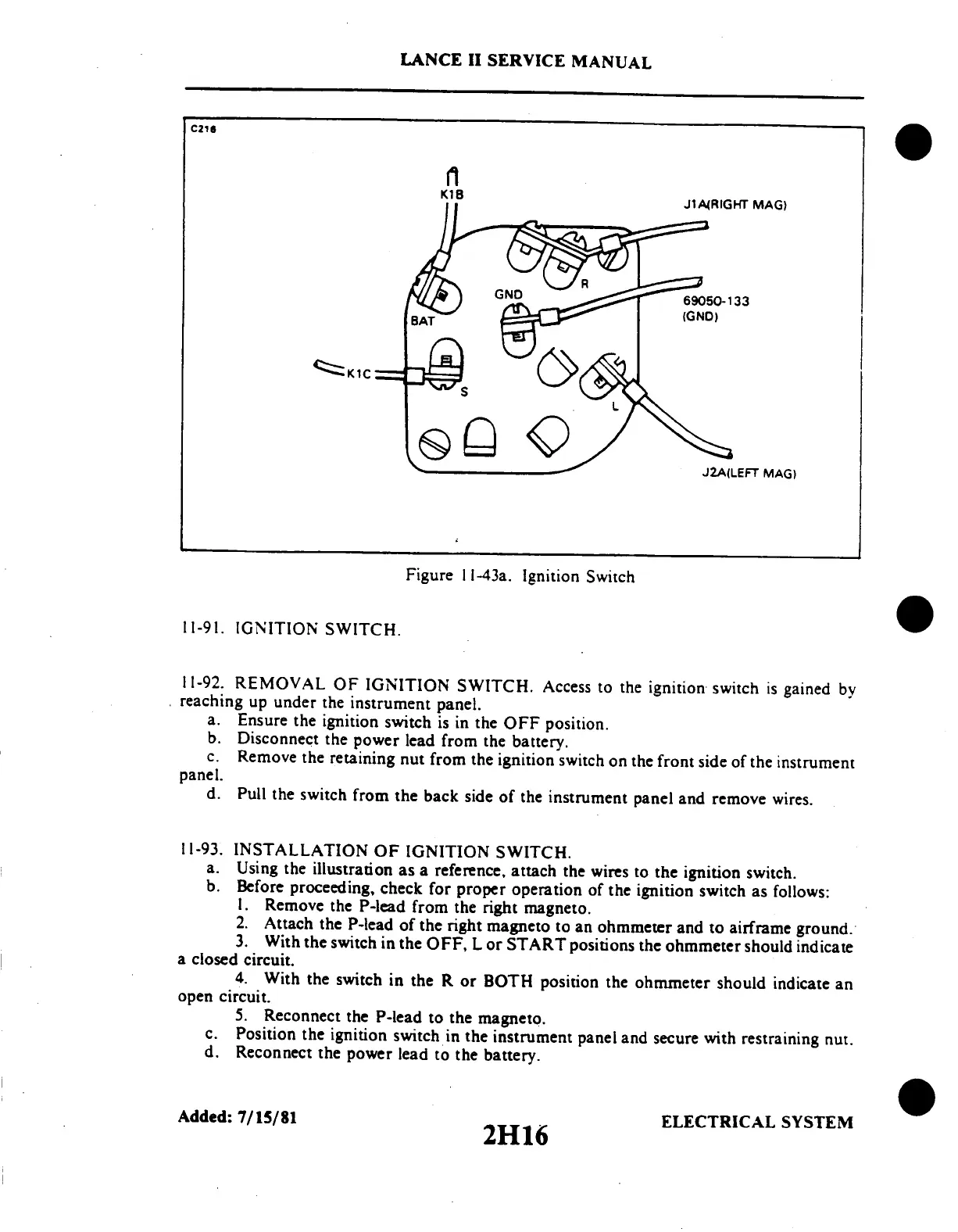
K1B
J1A4RIGHT MAG)
Figure
11-43a.
Ignition
Switch
11-91.
IGNITION
SWITCH.
11-92.
REMOVAL
OF
IGNITION
SWITCH.
Access
to
the
ignition
switch
is
gained
by
reaching
up
under
the
instrument
panel.
a.
Ensure
the
ignition
switch
is
in
the
OFF
position.
b.
Disconnect
the
power
lead
from
the
battery.
c.
Remove
the
retaining
nut
from
the
ignition
switch
on
the
front
side
of
the
instrument
panel.
d.
Pull
the
switch
from
the
back
side
of
the
instrument
panel
and
remove
wires.
11-93.
INSTALLATION
OF
IGNITION
SWITCH.
a.
Using
the
illustration
as
a
reference,
attach
the
wires
to
the
ignition
switch.
b.
Before
proceeding,
check
for
proper
operation
of
the
ignition
switch
as
follows:
1.
Remove
the
P-lead
from
the
right
magneto.
2.
Attach
the
P-lead
of
the
right
magneto
to
an
ohmmeter
and
to
airframe
ground.
3.
With
the
switch
in
the
OFF,
L
or
START
positions
the
ohmmeter
should
indicate
a
closed
circuit.
4.
With
the
switch
in
the
R
or
BOTH
position
the
ohmmeter
should
indicate
an
open
circuit.
5.
Reconnect
the
P-lead
to
the
magneto.
c.
Position
the
ignition
switch
in
the
instrument
panel
and
secure
with
restraining
nut.
d.
Reconnect
the
power
lead
to
the
battery.
Added:
7/15/81
ELECTRICAL
SYSTEM
LANCE
II
SERVICE
MANUAL
2H16

Table of Contents

Questions and Answers:

Question and Answer IconNeed help?

Do you have a question about the Piper PA-32RT-300T and is the answer not in the manual?

Piper PA-32RT-300T Specifications

General IconGeneral
BrandPiper
ModelPA-32RT-300T
CategoryAircrafts
LanguageEnglish

Related product manuals