B. Demonstrating closed-loop control to track a predetermined path
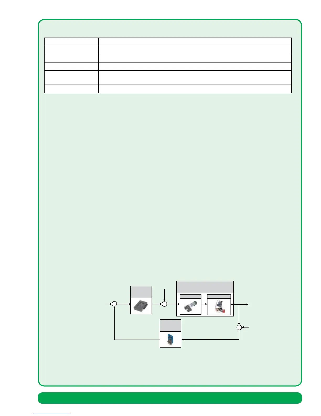
A closed-loop feedback control system utilizes a negative feedback loop with a sensor to measure the output and
compare the measured output, represented by Y(s), with the reference input, represented by R(s), to generate an
error signal, represented by Ea(s), that drives the controller. If we can utilize the error signal appropriately, then we
will achieve our tracking objective, that is, minimize E(s)=Y(s)-R(s), in the presence of external disturbances and plant
uncertainties and parameter changes. This is the key objective of closed-loop feedback controller design. The IR sensor
can used to distinguish between colors based on differences in IR reflectivity to track a prescribed path marked on the
ground. It can also measure the distance to obstacles allowing us to miss obstacles or track a prescribed path through
an obstructed area. With the introduction of the sensor, we have additional unwanted sensor noise, represented by
N(s). The main benefits of closed-loop control include (i) increased robustness of the closed-loop performance to
changes in the parameters of the plant, (ii) improved external disturbance rejection, measurement noise attenuation,
and reduction of the steady-state error of the system, and (iii) ready control and adjustment of the transient response
of the system by skillful design of the controller. However, these advantages come with cost. The main cost of closed-
loop feedback control is additional complexity that means higher monetary costs and greater likelihood of component
failures. Since the benefits far outweigh the disadvantages, we find closed-loop feedback control is widely employed
in modern control systems. The key to closed-loop feedback control is the use of the tracking error signal to improve
the transient response (settling time, percent overshoot, etc.) as well as reduce steady-state errors tracking errors.
Note: Control concepts described in detail in Modern Control Systems, by R. C. Dorf & R. H. Bishop, 13th Ed., Pearson
Education, Inc., 2017.
Figure 2 Closed-loop control of the rover with IR sensor feedback.
Plant Rover vehicle
Sensor Infrared (IR) range finder
Actuator DC servo motors
Performance Command following in the presence of disturbances
Design objectives Tune the control system by adjusting PID gain constants & track the predetermined
path
Reference inputs Predetermined path with obstacles
Y(s)
Plant
Controller
G
c
(s)
G(s)
Actuator
Balancing Robot
T
d
(s)
R(s)=0
Sensor
H(s)
-
N(s)
E
a
(s)
from vertical
Actual angle
from vertical
Rover Vehicle Assembly 81